Analog Devices LT8390 | Demoboard LT Journal
60V Synchronous 4-Switch Buck-Boost Controller with Spread Spectrum
Details
| Topologie | Abwärts- und Aufwärtswandler |
| Eingangsspannung | 0-48 V |
| Schaltfrequenz | 150-650 kHz |
| Ausgang 1 | 12 V |
| IC-Revision | 1 |
Beschreibung
The LT®8390 is a synchronous 4-switch buck-boost DC/DCcontroller that regulates output voltage, input or outputcurrent from an input voltage above, below, or equal tothe output voltage. The proprietary peak-buck/peak-boostcurrent mode control scheme allows adjustable and synchronizable150kHz to 650kHz fixed frequency operation, orinternal ±15% triangle spread spectrum frequency modulationfor low EMI. With a 4V to 60V input voltage range, 0Vto 60V output voltage capability, and seamless low-noisetransitions between operation regions, the LT8390 is idealfor voltage regulator, battery and supercapacitor chargerapplications in automotive, industrial, telecom, and evenbattery-powered systems.The LT8390 provides input or output current monitor andpower good flag. Fault protection is also provided to detectoutput short-circuit condition, during which the LT8390retries, latches off, or keeps running.
Eigenschaften
4-Switch Single Inductor Architecture Allows VIN Above, Below or Equal to VOUTSynchronous Switching: Up to 98% EfficiencyProprietary Peak-Buck Peak-Boost Current ModeWide VIN Range: 4V to 60V±1.5% Output Voltage Accuracy: 1V ≤ VOUT ≤ 60V±3% Input or Output Current Accuracy with MonitorSpread Spectrum Frequency Modulation for Low EMIHigh Side PMOS Load Switch DriverIntegrated Bootstrap DiodesNo Top MOSFET Refresh Noise in Buck or BoostAdjustable and Synchronizable: 150kHz to 650kHzVOUT Disconnected from VIN During ShutdownAvailable in 28-Lead TSSOP with Exposed Pad and 28-Lead QFN (4mm × 5mm)
Typische Anwendungen
- Automotive, Industrial, Telecom Systems
- High Power Battery-Powered System
Weiterführende Informationen
Artikeldaten
| Artikel Nr. | Datenblatt | Simulation | Downloads | Status | Produktserie | L (µH) | IRP,40K (A) | ISAT,10% (A) | ISAT,30% (A) | RDC (mΩ) | fres (MHz) | Material | Drahttype | Z @ 100 MHz (Ω) | Zmax (Ω) | Testbedingung Zmax | IR 2 (mA) | RDC max. (mΩ) | Typ | Muster | |
|---|---|---|---|---|---|---|---|---|---|---|---|---|---|---|---|---|---|---|---|---|---|
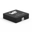
 | 744314150 | SPEC | 9 Dateien | Aktiv i| Produktion ist aktiv. Erwartete Lebenszeit: >10 Jahre. | WE-HCI SMT-Hochstrominduktivität | 1.5 | 16.4 | 4 | 11 | 4.3 | 110 | Superflux | – | – | – | – | – | 4.73 | – | ||
 | 744325420 | SPEC | 9 Dateien | Aktiv i| Produktion ist aktiv. Erwartete Lebenszeit: >10 Jahre. | WE-HCI SMT-Hochstrominduktivität | 4.2 | 15.4 | 5 | 14 | 7.1 | 33 | Superflux | – | – | – | – | – | 7.87 | – | ||
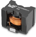
 | 7443640470 | SPEC | 9 Dateien | Aktiv i| Produktion ist aktiv. Erwartete Lebenszeit: >10 Jahre. | WE-HCF SMT-Hochstrominduktivität | 4.7 | 34.95 | 70 | 78 | 2.4 | 20 | MnZn | Flach | – | – | – | – | 2.64 | – | ||
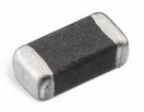
 | 742792118 | SPEC | 9 Dateien | Aktiv i| Produktion ist aktiv. Erwartete Lebenszeit: >10 Jahre. | WE-CBF SMT-Ferrit | – | – | – | – | – | – | – | – | 600 | 650 | 80 MHz | 2500 | 70 | Hochstrom |
| Muster |
|---|
| Artikel Nr. | Datenblatt | Simulation | Downloads | Status | Produktserie | L (µH) | IRP,40K (A) | ISAT,10% (A) | ISAT,30% (A) | RDC (mΩ) | fres (MHz) | Material | Drahttype | Z @ 100 MHz (Ω) | Zmax (Ω) | Testbedingung Zmax | IR 2 (mA) | RDC max. (mΩ) | Typ | Muster |
|---|


