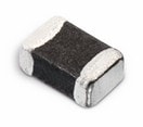
Details
| Topologie | Abwärtswandler |
| IC-Revision | C |
Beschreibung
Incorporates the ARM926EJ-S™ ARM® Thumb® Processor– DSP Instruction Extensions– ARM Jazelle® Technology for Java® Acceleration– 4 Kbyte Data Cache, 4 Kbyte Instruction Cache, Write Buffer– 210 MIPS at 190 MHz– Memory Management Unit– EmbeddedICE™ In-circuit Emulation, Debug Communication Channel Support– Mid-level implementation Embedded Trace Macrocell™???? Multi-layer AHB Bus Matrix for Large Bandwidth Transfers– Six 32-bit-layer Matrix– Boot Mode Select Option, Remap Command???? One 32-KByte internal ROM, Single-cycle Access at Maximum Speed???? One 64-KByte internal SRAM, Single-cycle Access at Maximum Speed– 4 Blocks of 16 Kbytes Configurable in TCM or General-purpose SRAM on the AHB Bus Matrix???? Single-cycle Accessible on AHB Bus at Bus Speed???? Single-cycle Accessible on TCM Interface at Processor Speed???? 2-channel DMA– Memory to Memory Transfer– 16 Bytes FIFO– LInked List???? External Bus Interface (EBI)– EBI Supports SDRAM, Static Memory, ECC-enabled NAND Flash and CompactFlash®???? LCD Controller– Supports Passive or Active Displays– Up to 24 Bits per Pixel in TFT Mode, Up to 16 bits per Pixel in STN Color Mode– Up to 16M Colors in TFT Mode, Resolution Up to 2048x2048, Virtual Screen Support???? High Speed (480 Mbit/s) USB 2.0 Device Controller– On-Chip High Speed Transceiver, UTMI+ Physical Interface– Integrated FIFOs and Dedicated DMA– 4 Kbyte Configurable Integrated DPRAM???? Fully-featured System Controller, including– Reset Controller, Shutdown ControllerBoard Description3-2 AT91SAM9RL-EK Evaluation Board User Guide6325C–ATARM–22-Jul-10– Four 32-bit Battery Backup Registers for a Total of 16 Bytes– Clock Generator and Power Management Controller– Advanced Interrupt Controller and Debug Unit– Periodic Interval Timer, Watchdog Timer and Real-time Timer and Real-time Clock???? Reset Controller (RSTC)– Based on Two Power-on Reset Cells– Reset Source Identification and Reset Output Control???? Shutdown Controller (SHDC)– Programmable Shutdown Pin Control and Wake-up Circuitry???? Clock Generator (CKGR)– Selectable 32768 Hz Low-power oscillator or Internal Low-power RC Oscillator on BatteryBackup Power Supply, Providing a Permanent Slow Clock– 12 MHz On-chip Oscillator for Main System Clock and USB Clock– One PLL up to 240 MHz– One PLL 480 MHz Optimized for USB HS???? Power Management Controller (PMC)– Very Slow Clock Operating Mode, Software Programmable Power Optimization Capabilities– Two Programmable External Clock Signals???? Advanced Interrupt Controller (AIC)– Individually Maskable, Eight-level Priority, Vectored Interrupt Sources– One External Interrupt Sources and One Fast Interrupt Source, Spurious Interrupt Protected???? Debug Unit (DBGU)– 2-wire UART and support for Debug Communication Channel???? Periodic Interval Timer (PIT)– 20-bit interval timer plus 12-bit interval counter???? Watchdog Timer (WDT)– Key-protected, Programmable Only Once, Windowed 16-bit Counter Running at Slow Clock???? Real-time Timer (RTT)– 32-bit Free-running Backup Counter Running at Slow Clock with 16-bit Prescaler???? Real-time Clock (RTC)– Time, Date and Alarm 32-bit Parallel Load– Low Power Consumption– Programmable Periodic Interrupt???? One 6-channel 10-Bit Analog-to-Digital Converter– Touch Screen Interface Compatible with Industry Standard 4-wire Sensitive Touch Panels???? Four 32-bit Parallel Input/Output Controllers (PIOA, PIOB, PIOC and PIOD)– 118 Programmable I/O Lines Multiplexed with up to Two Peripheral I/Os for 217-ball BGA package– Input Change Interrupt Capability on Each I/O Line– Individually Programmable Open-drain, Pull-up resistor and Synchronous Output???? 24-channel Peripheral DMA Controller (PDC)???? One Multimedia Card Interface (MCI)– SDCard/SDIO 1.0 and MultiMedia Card 3.1 CompliantBoard DescriptionAT91SAM9RL-EK Evaluation Board User Guide 3-36325C–ATARM–22-Jul-10– Automatic Protocol Control and Fast Automatic Data Transfers with PDC???? Two Synchronous Serial Controllers (SSC)– Independent Clock and Frame Sync Signals for Each Receiver and Transmitter– I²S Analog Interface Support, Time Division Multiplex Support– High-speed Continuous Data Stream Capabilities with 32-bit Data Transfer???? One AC97 Controller (AC97C)– 6-channel Single AC97 Analog Front End Interface, Slot Assigner???? Four Universal Synchronous/Asynchronous Receiver Transmitters (USART)– Individual Baud Rate Generator, IrDA Infrared Modulation/Demodulation, ManchesterEncoding/Decoding– Support for ISO7816 T0/T1 Smart Card, Hardware Handshaking, RS485 Support???? One Master/Slave Serial Peripheral Interface (SPI)– 8- to 16-bit Programmable Data Length, Four External Peripheral Chip Selects– High-speed Synchronous Communications???? One Three-channel 16-bit Timer/Counter (TC)– Three External Clock Inputs, Two Multi-purpose I/O Pins per Channel– Double PWM Generation, Capture/Waveform Mode, Up/Down Capability???? One Four-channel 16-bit PWM Controller (PWMC)???? Two Two-wire Interfaces (TWI)– Compatible with Standard Two-wire Serial Memories– One, Two or Three Bytes for Slave Address– Sequential Read/Write Operations– Master, Multi-master and Slave Mode Operation– Bit Rate: Up to 400 Kbits– General Call Supported in Slave mode– Connection to Peripheral DMA Controller (PDC) Channel Capabilities Optimizes Data Transfersin Master Mode Only (TWI0 only)???? SAM-BA Boot Assistant– Default Boot Program– Interface with SAM-BA Graphic User Interface???? IEEE 1149.1 JTAG Boundary Scan on All Digital Pins???? Required Power Supplies:– 1.08 to 1.32V for VDDCORE, VDDPLLB and VDDBU– 3.0V to 3.6V for VDDPLLA, VDDANA, VDDUTMI and VDDIOP– Programmable 1.65V to 1.95V or 3.0V to 3.6V for VDDIOM???? Available in a 144-ball BGA (AT91SAM9R64) and a 217-ball LFBGA (AT91SAM9RL64) Package
Eigenschaften
– Reset Controller, Shutdown Controller
– Four 32-bit Battery Backup Registers for a Total of 16 Bytes
– Clock Generator and Power Management
– Advanced Interrupt Controller and Debug Unit
– Periodic Interval Timer, Watchdog Timer and Real-time Timer and Real-time Clock
Typische Anwendungen
- LCD Controller
Weiterführende Informationen
Artikeldaten
| Artikel Nr. | Datenblatt | Simulation | Downloads | Status | Produktserie | Z @ 100 MHz (Ω) | Zmax (Ω) | Testbedingung Zmax | IR 2 (mA) | RDC max. (Ω) | Typ | Muster | |
|---|---|---|---|---|---|---|---|---|---|---|---|---|---|
 | 742792093 | SPEC | 9 Dateien | Aktiv i| Produktion ist aktiv. Erwartete Lebenszeit: >10 Jahre. | WE-CBF SMT-Ferrit | 2200 | 3000 | 80 MHz | 800 | 0.6 | Breitband |
| Muster |
|---|
| Artikel Nr. | Datenblatt | Simulation | Downloads | Status | Produktserie | Z @ 100 MHz (Ω) | Zmax (Ω) | Testbedingung Zmax | IR 2 (mA) | RDC max. (Ω) | Typ | Muster |
|---|


