Details
| Topologie | Sonstige Topologie |
| IC-Revision | 3 |
Beschreibung
The EV37F82A is intended to act as a reference design for the MCP1012, implementing a complete design with secondary microcontroller. The MCP1012 15W Reference Design demonstrates the ability of the MCP1012 (located on the primary side) to start up a 15W AC-DC Flyback Converter and then have it commanded by a microcontroller (located on the secondary side).The MCP1012 15W Reference Design provides a hardware and software platform to evaluate a novel method of isolated secondary side control. Two key components enable the startup and secondary side regulation of an isolated power supply, the Microchip MCP1012 and the Microchip patented integrated magnetic winding transformer built by Wurth Electronic.
Eigenschaften
- MCP1012 uses an open-loop, constant off-time, peak current-mode current regulator
- MCP1012 uses a high voltage silicon process (0.5µ 5v/30v/700v) to develop a High Voltage (HV) Linear Regulator. The HV Linear Regulator will be rated for 700V, with an input at VIN and a regulated bias output at VDD.
- VDD is monitored by an Under-voltage Lockout (UVLO) feature
- VDD is monitored by an Over-voltage Lockout (OVLO) feature
- The device’s internal open-loop, peak current-mode current regulator operates in constant Off-Time mode. The duration of the Off-Time is internally fixed at 20µs typical
- MCP1012 provides a MOSFET Gate Driver (GATE)
- The Gate Driver can be commanded either by the internal open-loop, constant off-time peak current-mode current regulator circuitry or by an external PWM command via PULSE
Weiterführende Informationen
Artikeldaten
| Artikel Nr. | Datenblatt | Simulation | Downloads | Status | Produktserie | Pins (pcs) | Anwendung | PCB/Kabel/Panel | Modularity | Wire Section | C | Sicherheitsklasse | dV/dt (V/µs) | DF @ 1 kHz (%) | RISO | Raster (mm) | Verpackung | Tol. C | Bauform | Betriebstemperatur | Q (%) | DF (%) | Keramiktyp | Fl (mm) | IRP,40K (A) | ISAT (A) | fres (MHz) | Version | Endurance (h) | IRIPPLE (mA) | ILeak (µA) | Ø D (mm) | Z (mΩ) | Z @ 100 MHz (Ω) | Zmax (Ω) | Testbedingung Zmax | IR 2 (mA) | RDC max. (mΩ) | Typ | IR (A) | L (µH) | VR (V (AC)) | VT (V (AC)) | Material | L (mm) | W (mm) | H (mm) | Montageart | Muster | |
|---|---|---|---|---|---|---|---|---|---|---|---|---|---|---|---|---|---|---|---|---|---|---|---|---|---|---|---|---|---|---|---|---|---|---|---|---|---|---|---|---|---|---|---|---|---|---|---|---|---|---|
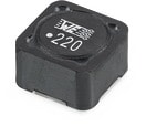
 | 7447779115 | SPEC | 9 Dateien | Aktiv i| Produktion ist aktiv. Erwartete Lebenszeit: >10 Jahre. | WE-PD SMT-Speicherdrossel | 2 | – | – | – | – | – | – | – | – | – | – | – | – | 7345 | -40 °C up to +125 °C | – | – | – | – | 2.8 | 2.2 | 19.5 | Robust | – | – | – | – | – | – | – | – | – | 81 | – | 1.6 | 15 | – | – | – | 7.3 | 7.3 | 4.5 | SMT | ||
 | 691415520003 | SPEC | – | 6 Dateien | Aktiv i| Produktion ist aktiv. Erwartete Lebenszeit: >10 Jahre. | WR-TBL Series 4155 - 5.08 mm Screwless 45° Entry | 3 | Schraublos | PCB | Nein | 18 to 22 (AWG) 0.823 to 0.326 (mm²) | – | – | – | – | – | 5.08 | Karton | – | – | -30 °C up to +120 °C | – | – | – | – | – | – | – | – | – | – | – | – | – | – | – | – | – | – | 45° | 10 | – | – | – | – | 15.24 | – | – | THT | |
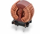
 | 744821240 | SPEC | 10 Dateien | Aktiv i| Produktion ist aktiv. Erwartete Lebenszeit: >10 Jahre. | WE-CMB Stromkompensierte Netzdrossel | 4 | – | – | – | – | – | – | – | – | – | – | – | – | XS | -40 °C up to +125 °C | – | – | – | – | – | – | – | THT | – | – | – | – | – | – | – | – | – | 140 | – | 1.5 | 4000 | 250 | 1500 | MnZn | 15.8 | 7.8 | 18 | THT | ||
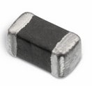
 | 742792624 | SPEC | 8 Dateien | Aktiv i| Produktion ist aktiv. Erwartete Lebenszeit: >10 Jahre. | WE-CBF SMT-Ferrit | – | – | – | – | – | – | – | – | – | – | – | – | – | 0603 | -55 °C up to +125 °C | – | – | – | 0.3 | – | – | – | SMT | – | – | – | – | – | 180 | 250 | 400 MHz | 1500 | 90 | Hochstrom | 1 | – | – | – | – | 1.6 | 0.8 | 0.8 | SMT | ||
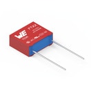
 | 890334025017CS | SPEC | 9 Dateien | Aktiv i| Produktion ist aktiv. Erwartete Lebenszeit: >10 Jahre. | WCAP-FTXX Folienkondensatoren | – | Across the mains | – | – | – | 100 nF | X2 | 300 | 0.1 | 30 GΩ | 15 | Karton | ±10% | Raster 15 mm | -40 °C up to +105 °C | – | – | – | – | – | – | – | – | – | – | – | – | – | – | – | – | – | – | – | – | – | 310 | – | – | 18 | 6 | 12 | Boxed THT | ||
 | 860241378003 | SPEC | 7 Dateien | Aktiv i| Produktion ist aktiv. Erwartete Lebenszeit: >10 Jahre. | WCAP-AT1H Aluminium-Elektrolytkondensatoren | – | – | – | – | – | 22 µF | – | – | – | – | 5 | Ammopack | ±20% | – | – | – | 20 | – | – | – | – | – | – | 10000 | 557 | 452 | 13 | – | – | – | – | – | – | – | – | – | 400 | – | – | 20 | – | – | – | ||
 | 865080257014 | SPEC | 9 Dateien | Aktiv i| Produktion ist aktiv. Erwartete Lebenszeit: >10 Jahre. | WCAP-ASLI Aluminium-Elektrolytkondensatoren | – | – | – | – | – | 1000 µF | – | – | – | 0.1 MΩ | – | 15" Tape & Reel | ±20% | 10.0 x 10.5 | -55 °C up to +105 °C | – | 19 | – | – | – | – | – | SMT | 2000 | 740 | 100 | 10 | 150 | – | – | – | – | – | – | – | – | 10 | – | – | 10.5 | 10.3 | – | V-Chip SMT | ||
| 885012006042 | SPEC | 9 Dateien | Aktiv i| Produktion ist aktiv. Erwartete Lebenszeit: >10 Jahre. | WCAP-CSGP MLCCs 25 V(DC) | – | – | – | – | – | 470 pF | – | – | – | 10 GΩ | – | 7" Tape & Reel | ±5% | 0603 | -55 °C up to +125 °C | 1000 | – | NP0 Klasse I | 0.4 | – | – | – | – | – | – | – | – | – | – | – | – | – | – | – | – | – | 25 | – | – | 1.6 | 0.8 | 0.8 | – | |||
| 885012206076 | SPEC | 9 Dateien | Aktiv i| Produktion ist aktiv. Erwartete Lebenszeit: >10 Jahre. | WCAP-CSGP MLCCs 25 V(DC) | – | – | – | – | – | 1 µF | – | – | – | 0.5 GΩ | – | 7" Tape & Reel | ±10% | 0603 | -55 °C up to +125 °C | – | 10 | X7R Klasse II | 0.4 | – | – | – | – | – | – | – | – | – | – | – | – | – | – | – | – | – | 25 | – | – | 1.6 | 0.8 | 0.8 | – | |||
| 885012206089 | SPEC | 9 Dateien | Aktiv i| Produktion ist aktiv. Erwartete Lebenszeit: >10 Jahre. | WCAP-CSGP MLCCs 50 V(DC) | – | – | – | – | – | 10 nF | – | – | – | 10 GΩ | – | 7" Tape & Reel | ±10% | 0603 | -55 °C up to +125 °C | – | 2.5 | X7R Klasse II | 0.4 | – | – | – | – | – | – | – | – | – | – | – | – | – | – | – | – | – | 50 | – | – | 1.6 | 0.8 | 0.8 | – | |||
| 885012007063 | SPEC | 9 Dateien | Aktiv i| Produktion ist aktiv. Erwartete Lebenszeit: >10 Jahre. | WCAP-CSGP MLCCs 50 V(DC) | – | – | – | – | – | 1 nF | – | – | – | 10 GΩ | – | 7" Tape & Reel | ±5% | 0805 | -55 °C up to +125 °C | 1000 | – | NP0 Klasse I | 0.5 | – | – | – | – | – | – | – | – | – | – | – | – | – | – | – | – | – | 50 | – | – | 2 | 1.25 | 0.8 | – | |||
| 885012208069 | SPEC | 9 Dateien | Aktiv i| Produktion ist aktiv. Erwartete Lebenszeit: >10 Jahre. | WCAP-CSGP MLCCs 25 V(DC) | – | – | – | – | – | 10 µF | – | – | – | 0.01 GΩ | – | 7" Tape & Reel | ±10% | 1206 | -55 °C up to +125 °C | – | 10 | X7R Klasse II | 0.5 | – | – | – | – | – | – | – | – | – | – | – | – | – | – | – | – | – | 25 | – | – | 3.2 | 1.6 | 1.6 | – | |||
| 885012109014 | SPEC | 9 Dateien | Aktiv i| Produktion ist aktiv. Erwartete Lebenszeit: >10 Jahre. | WCAP-CSGP MLCCs 25 V(DC) | – | – | – | – | – | 22 µF | – | – | – | 0.005 GΩ | – | 7" Tape & Reel | ±20% | 1210 | -55 °C up to +85 °C | – | 10 | X5R Klasse II | 0.6 | – | – | – | – | – | – | – | – | – | – | – | – | – | – | – | – | – | 25 | – | – | 3.2 | 2.5 | 2.5 | – | |||
| 885012006079 | SPEC | 7 Dateien | Aktiv i| Produktion ist aktiv. Erwartete Lebenszeit: >10 Jahre. | WCAP-CSGP MLCCs 100 V(DC) | – | – | – | – | – | 100 pF | – | – | – | 10 GΩ | – | 7" Tape & Reel | ±5% | 0603 | -55 °C up to +125 °C | 1000 | – | NP0 Klasse I | 0.4 | – | – | – | – | – | – | – | – | – | – | – | – | – | – | – | – | – | 100 | – | – | 1.6 | 0.8 | 0.8 | – | |||
| 885012206111 | SPEC | 7 Dateien | Aktiv i| Produktion ist aktiv. Erwartete Lebenszeit: >10 Jahre. | WCAP-CSGP MLCCs 100 V(DC) | – | – | – | – | – | 3.3 nF | – | – | – | 10 GΩ | – | 7" Tape & Reel | ±10% | 0603 | -55 °C up to +125 °C | – | 2.5 | X7R Klasse II | 0.4 | – | – | – | – | – | – | – | – | – | – | – | – | – | – | – | – | – | 100 | – | – | 1.6 | 0.8 | 0.8 | – | |||
 | 750318659 | SPEC | – | – | Aktiv i| Produktion ist aktiv. Erwartete Lebenszeit: >10 Jahre. | Offline Transformer | – | – | – | – | – | – | – | – | – | – | – | – | – | – | – | – | – | – | – | – | – | – | – | – | – | – | – | – | – | – | – | – | – | – | – | – | – | – | – | 27.05 | 32.25 | 22.86 | – |
| Muster |
|---|
| Artikel Nr. | Datenblatt | Simulation | Downloads | Status | Produktserie | Pins (pcs) | Anwendung | PCB/Kabel/Panel | Modularity | Wire Section | C | Sicherheitsklasse | dV/dt (V/µs) | DF @ 1 kHz (%) | RISO | Raster (mm) | Verpackung | Tol. C | Bauform | Betriebstemperatur | Q (%) | DF (%) | Keramiktyp | Fl (mm) | IRP,40K (A) | ISAT (A) | fres (MHz) | Version | Endurance (h) | IRIPPLE (mA) | ILeak (µA) | Ø D (mm) | Z (mΩ) | Z @ 100 MHz (Ω) | Zmax (Ω) | Testbedingung Zmax | IR 2 (mA) | RDC max. (mΩ) | Typ | IR (A) | L (µH) | VR (V (AC)) | VT (V (AC)) | Material | L (mm) | W (mm) | H (mm) | Montageart | Muster |
|---|


