STMicroelectronics STM32F413RH | Demoboard EVALST-PLCMB1
High-performance access line, ARM Cortex-M4 core with DSP and FPU, 1,5 MByte Flash, 100 MHz CPU, ART Accelerator, DFSDM
Details
| Topologie | Sonstige Topologie |
| IC-Revision | 211 |
Beschreibung
The STM32F413xG/H devices are based on the high-performance Arm® Cortex®-M4 32-bit RISC core operating at a frequency of up to 100 MHz. Their Cortex®-M4 core features a Floating point unit (FPU) single precision which supports all Arm single-precision data-processing instructions and data types. It also implements a full set of DSP instructions and a memory protection unit (MPU) which enhances application security.The STM32F413xG/H devices belong to the STM32F4 access product lines (with products combining power efficiency, performance and integration) while adding a new innovative feature called Batch Acquisition Mode (BAM) allowing to save even more power consumption during data batching.The STM32F413xG/H devices incorporate high-speed embedded memories (up to 1.5 Mbytes of Flash memory, 320 Kbytes of SRAM), and an extensive range of enhanced I/Os and peripherals connected to two APB buses, three AHB buses and a 32-bit multi-AHB bus matrix.All devices offer a 12-bit ADC, two 12-bit DACs, a low-power RTC, twelve general-purpose 16-bit timers including two PWM timer for motor control, two general-purpose 32-bit timers and a low power timer.They also feature standard and advanced communication interfaces.
Eigenschaften
- Dynamic Efficiency Line with eBAM (enhanced Batch Acquisition Mode)
- 1.7 V to 3.6 V power supply
- -40 °C to 85/105/125 °C temperature range
- Core: Arm® 32-bit Cortex®-M4 CPU with FPU, Adaptive real-time accelerator (ART Accelerator™) allowing 0-wait state execution from Flash memory, frequency up to 100 MHz, memory protection unit, 125 DMIPS/ 1.25 DMIPS/MHz (Dhrystone 2.1), and DSP instructions
- Memories-Up to 1.5 Mbytes of Flash memory-320 Kbytes of SRAM-Flexible external static memory controller with up to 16-bit data bus: SRAM, PSRAM, NOR Flash memory
- Dual mode Quad-SPI interface
- LCD parallel interface, 8080/6800 modes
- Clock, reset and supply management
- 1.7 to 3.6 V application supply and I/Os
- POR, PDR, PVD and BOR
- 4-to-26 MHz crystal oscillator
- Internal 16 MHz factory-trimmed RC
- 32 kHz oscillator for RTC with calibration
- Internal 32 kHz RC with calibration
- Power consumption
- Run: 112 μA/MHz (peripheral off)
- Stop (Flash in Stop mode, fast wakeup time): 42 μA Typ.; 80 μA max @25 °C
- Stop (Flash in Deep power down mode, slow wakeup time): 15 μA Typ.; 46 μA max @25 °C
- Standby without RTC: 1.1 μA Typ.; 14.7 μA max at @85 °C
- VBAT supply for RTC: 1 μA @25 °C
- 2x12-bit D/A converters
- 1×12-bit, 2.4 MSPS ADC: up to 16 channels
- 6x digital filters for sigma delta modulator, 12x PDM interfaces, with stereo microphone and sound source localization support
- General-purpose DMA: 16-stream DMA
- Up to 18 timers: up to twelve 16-bit timers, two 32-bit timers up to 100 MHz each with up to four IC/OC/PWM or pulse counter and quadrature (incremental) encoder input, two watchdog timers (independent and window), one SysTick timer, and a low-power timer
- Debug mode
- Serial wire debug (SWD) & JTAG
- Cortex®-M4 Embedded Trace Macrocell™
- Up to 114 I/O ports with interrupt capability
- Up to 109 fast I/Os up to 100 MHz
- Up to 114 five V-tolerant I/Os
- Up to 24 communication interfaces
- Up to 4x I2C interfaces (SMBus/PMBus)
- Up to 10 UARTS: 4 USARTs / 6 UARTs (2 x 12.5 Mbit/s, 2 x 6.25 Mbit/s), ISO 7816 interface, LIN, IrDA, modem control)
- Up to 5 SPI/I2Ss (up to 50 Mbit/s, SPI or I2S audio protocol), out of which 2 muxed full-duplex I2S interfaces
- SDIO interface (SD/MMC/eMMC)
- Advanced connectivity: USB 2.0 full-speed device/host/OTG controller with PHY
- 3x CAN (2.0B Active)
- 1xSAI
- True random number generator
- CRC calculation unit
- 96-bit unique ID
- RTC: subsecond accuracy, hardware calendar
- All packages are ECOPACK®2
Typische Anwendungen
- Industrial applications: PLC, inverters, circuit breakers
- Wearable devices
- Wifi modules
- Alarm systems, video intercom, and HVAC
- Motor drive and application control
- Medical equipment
Weiterführende Informationen
Artikeldaten
| Artikel Nr. | Datenblatt | Simulation | Downloads | Status | Produktserie | Pins (pcs) | Anwendung | PCB/Kabel/Panel | Modularity | Wire Section | λDom typ. (nm) | Farbe | λPeak typ. (nm) | IV typ. (mcd) | VF typ. (V) | Chiptechnologie | 2θ50% typ. (°) | IR (A) | RDC (Ω) | Mittelstift Ø (Value) (mm) | Plug OD (mm) | Arbeitsspannung (V (AC)) | Verpackung | Raster (mm) | Version | Gender | Reihen | Montageart | L (mm) | Betriebstemperatur | Kontaktwiderstand (mΩ) | Tol. R | Stranded Wire Section (AWG) | Farbe | H (mm) | Betätigungskraft (g) | Elektrische Lebensdauer (Cycles) | Actuator-Farbe | Dampfphasenprozess | Z @ 100 MHz (Ω) | Zmax (Ω) | Testbedingung Zmax | IR 2 (mA) | RDC max. (Ω) | Typ | Muster | |
|---|---|---|---|---|---|---|---|---|---|---|---|---|---|---|---|---|---|---|---|---|---|---|---|---|---|---|---|---|---|---|---|---|---|---|---|---|---|---|---|---|---|---|---|---|---|---|---|
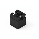 | 60900213621 | SPEC | – | 3 Dateien | Aktiv i| Produktion ist aktiv. Erwartete Lebenszeit: >10 Jahre. | WR-PHD Jumper | 1 | – | – | – | – | – | – | – | – | – | – | – | 3 | – | – | – | 250 | Beutel | 2.54 | – | Jumper | – | – | 2.44 | -40 °C up to +125 °C | 20 | max. | – | Blau | – | – | – | – | – | – | – | – | – | – | – | |
 | 691216510002S | SPEC | – | 6 Dateien | Aktiv i| Produktion ist aktiv. Erwartete Lebenszeit: >10 Jahre. | WR-TBL Serie 2165S - 5.08 mm Horizontal Entry Modular w. Rising Cage Clamp | 2 | Käfigzugklemme | PCB | Ja | 12 to 30 (AWG) 3.31 to 0.0509 (mm²) | – | – | – | – | – | – | – | 24 | – | – | – | 250 | Karton | 5.08 | – | – | – | THT | 10.16 | -30 °C up to +120 °C | 20 | max. | 12 to 30 (AWG) | Grün | – | – | – | – | – | – | – | – | – | – | Horizontal | |
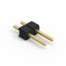 | 61300211121 | SPEC | – | 7 Dateien | Aktiv i| Produktion ist aktiv. Erwartete Lebenszeit: >10 Jahre. | WR-PHD Pin Header - Single | 2 | – | – | – | – | – | – | – | – | – | – | – | 3 | – | – | – | 250 | Beutel | 2.54 | – | Stiftleiste | Single | THT | 5.08 | -40 °C up to +105 °C | 20 | max. | – | – | – | – | – | – | – | – | – | – | – | – | Gerade | |
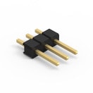 | 61300311121 | SPEC | – | 7 Dateien | Aktiv i| Produktion ist aktiv. Erwartete Lebenszeit: >10 Jahre. | WR-PHD Pin Header - Single | 3 | – | – | – | – | – | – | – | – | – | – | – | 3 | – | – | – | 250 | Beutel | 2.54 | – | Stiftleiste | Single | THT | 7.62 | -40 °C up to +105 °C | 20 | max. | – | – | – | – | – | – | – | – | – | – | – | – | Gerade | |
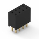 | 61300821821 | SPEC | – | 7 Dateien | Aktiv i| Produktion ist aktiv. Erwartete Lebenszeit: >10 Jahre. | WR-PHD Socket Header - Dual | 8 | – | – | – | – | – | – | – | – | – | – | – | 3 | – | – | – | 250 | Tray | 2.54 | – | Buchsenleiste | Dual | THT | 10.66 | -40 °C up to +105 °C | 20 | max. | – | – | – | – | – | – | – | – | – | – | – | – | Gerade | |
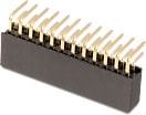 | 613012243121 | SPEC | – | 7 Dateien | Aktiv i| Produktion ist aktiv. Erwartete Lebenszeit: >10 Jahre. | WR-PHD Socket Header - Dual | 12 | – | – | – | – | – | – | – | – | – | – | – | 3 | – | – | – | 250 | Tray | 2.54 | – | Buchsenleiste | Dual | THT | 15.74 | -40 °C up to +105 °C | 20 | max. | – | Schwarz | – | – | – | – | – | – | – | – | – | – | Abgewinkelt | |
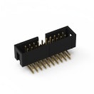 | 61202021721 | SPEC | – | 7 Dateien | Aktiv i| Produktion ist aktiv. Erwartete Lebenszeit: >10 Jahre. | WR-BHD 2.54 mm Male | 20 | – | PCB | – | – | – | – | – | – | – | – | – | 3 | – | – | – | 250 | Tray | 2.54 | Low Profile | Männlich | – | THT | 33.06 | -40 °C up to +105 °C | 20 | max. | – | – | – | – | – | – | – | – | – | – | – | – | Abgewinkelt | |
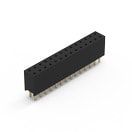 | 61302821821 | SPEC | – | 7 Dateien | Aktiv i| Produktion ist aktiv. Erwartete Lebenszeit: >10 Jahre. | WR-PHD Socket Header - Dual | 28 | – | – | – | – | – | – | – | – | – | – | – | 3 | – | – | – | 250 | Tray | 2.54 | – | Buchsenleiste | Dual | THT | 36.06 | -40 °C up to +105 °C | 20 | max. | – | – | – | – | – | – | – | – | – | – | – | – | Gerade | |
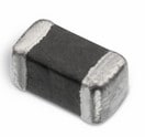 | 74279262 | SPEC | 9 Dateien | Aktiv i| Produktion ist aktiv. Erwartete Lebenszeit: >10 Jahre. | WE-CBF SMT-Ferrit | – | – | – | – | – | – | – | – | – | – | – | – | 0.5 | – | – | – | – | – | – | SMT | – | – | SMT | 1.6 | -55 °C up to +125 °C | – | – | – | – | 0.8 | – | – | – | – | 120 | 200 | 510 MHz | 1350 | 0.3 | Breitband | ||
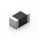 | 782631331 | SPEC | 10 Dateien | Aktiv i| Produktion ist aktiv. Erwartete Lebenszeit: >10 Jahre. | WE-CBA SMT EMI Suppression Ferrite Bead | – | – | – | – | – | – | – | – | – | – | – | – | 0.4 | 0.25 | – | – | – | – | – | SMT | – | – | SMT | 1.6 | -55 °C up to +125 °C | – | – | – | – | 0.8 | – | – | – | – | 330 | 690 | 280 MHz | – | – | Hochgeschwindigkeit | ||
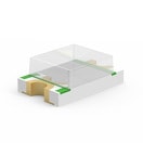 | 150080RS75000 | SPEC | 7 Dateien | Aktiv i| Produktion ist aktiv. Erwartete Lebenszeit: >10 Jahre. | WL-SMCW SMT Mono-color Chip LED Waterclear | – | – | – | – | – | 625 | Rot | 630 | 150 | 2 | AlInGaP | 140 | – | – | – | – | – | Tape and Reel | – | – | – | – | SMT | 2 | -40 °C up to +85 °C | – | – | – | – | 0.7 | – | – | – | – | – | – | – | – | – | – | ||
 | 150080VS75000 | SPEC | 7 Dateien | Aktiv i| Produktion ist aktiv. Erwartete Lebenszeit: >10 Jahre. | WL-SMCW SMT Mono-color Chip LED Waterclear | – | – | – | – | – | 570 | Hellgrün | 572 | 40 | 2 | AlInGaP | 140 | – | – | – | – | – | Tape and Reel | – | – | – | – | SMT | 2 | -40 °C up to +85 °C | – | – | – | – | 0.7 | – | – | – | – | – | – | – | – | – | – | ||
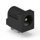 | 694106301002 | SPEC Anstehende PCNAufgrund einer anstehenden PCN wird sich in Kürze das Datenblatt des ausgewählten Produktes ändern. Anbei finden Sie das neue Datenblatt, sowie das noch gültige Datenblatt. Bei weiteren Fragen wenden Sie sich bitte an Ihren Vertriebsmitarbeiter. | – | 7 Dateien | Aktiv i| Produktion ist aktiv. Erwartete Lebenszeit: >10 Jahre. | WR-DC Power Jacks | – | – | – | – | – | – | – | – | – | – | – | – | 5 | – | 2 | 5.5 | 30 | Beutel | – | – | – | – | THT | – | -40 °C up to +85 °C | 50 | max. | – | Schwarz | – | – | – | – | – | – | – | – | – | – | Abgewinkelt | |
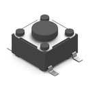 | 430182043816 | SPEC | – | 5 Dateien | Aktiv i| Produktion ist aktiv. Erwartete Lebenszeit: >10 Jahre. | WS-TASV SMT Tact Switch 6x6 mm | – | – | – | – | – | – | – | – | – | – | – | – | 0.05 | – | – | – | – | Tape and Reel | – | – | – | – | – | – | -40 °C up to +85 °C | – | – | – | – | 4.3 | 160 | 1000000 | Schwarz | nicht spezifiziert | – | – | – | – | – | – |
| Artikel Nr. | Datenblatt | Simulation | |
|---|---|---|---|
 | 60900213621 | SPEC | – |
 | 691216510002S | SPEC | – |
 | 61300211121 | SPEC | – |
 | 61300311121 | SPEC | – |
 | 61300821821 | SPEC | – |
 | 613012243121 | SPEC | – |
 | 61202021721 | SPEC | – |
 | 61302821821 | SPEC | – |
 | 74279262 | SPEC | |
 | 782631331 | SPEC | |
 | 150080RS75000 | SPEC | |
 | 150080VS75000 | SPEC | |
 | 694106301002 | SPEC Anstehende PCNAufgrund einer anstehenden PCN wird sich in Kürze das Datenblatt des ausgewählten Produktes ändern. Anbei finden Sie das neue Datenblatt, sowie das noch gültige Datenblatt. Bei weiteren Fragen wenden Sie sich bitte an Ihren Vertriebsmitarbeiter. | – |
 | 430182043816 | SPEC | – |
| Muster |
|---|
| Artikel Nr. | Datenblatt | Simulation | Downloads | Status | Produktserie | Pins (pcs) | Anwendung | PCB/Kabel/Panel | Modularity | Wire Section | λDom typ. (nm) | Farbe | λPeak typ. (nm) | IV typ. (mcd) | VF typ. (V) | Chiptechnologie | 2θ50% typ. (°) | IR (A) | RDC (Ω) | Mittelstift Ø (Value) (mm) | Plug OD (mm) | Arbeitsspannung (V (AC)) | Verpackung | Raster (mm) | Version | Gender | Reihen | Montageart | L (mm) | Betriebstemperatur | Kontaktwiderstand (mΩ) | Tol. R | Stranded Wire Section (AWG) | Farbe | H (mm) | Betätigungskraft (g) | Elektrische Lebensdauer (Cycles) | Actuator-Farbe | Dampfphasenprozess | Z @ 100 MHz (Ω) | Zmax (Ω) | Testbedingung Zmax | IR 2 (mA) | RDC max. (Ω) | Typ | Muster |
|---|


