Texas Instruments MSP430F5529 | Demoboard TIDA-00662
High Performance Capacitive Sensor Front End Reference Design
Details
| Topologie | Sonstige Topologie |
| Eingangsspannung | 5 V |
| Schaltfrequenz | 25000 kHz |
| IC-Revision | A |
Beschreibung
The Texas Instruments MSP430 family of ultra-low-power MCUs consists of several devices featuringdifferent sets of peripherals targeted for various applications. The architecture, combined with extensivelow-power modes, is optimized to achieve extended battery life in portable measurement applications. Thedevice features a powerful 16-bit RISC CPU, 16-bit registers, and constant generators that contribute tomaximum code efficiency. The digitally controlled oscillator (DCO) allows wake-up from low-power modesto active mode in 3.5 μs (typical). The MSP430F5529 is a MCU configuration with integrated USB andPHY supporting USB 2.0, four 16-bit timers, a high performance 12-bit ADC, two universal serialcommunication interfaces (USCI), hardware multiplier, DMA, real-time clock module with alarmcapabilities, and 63 I/O pins (see Figure 19). Typical applications include analog and digital sensorsystems, data loggers, and others that require connectivity to various USB hosts.
Eigenschaften
- Low supply-voltage range: 3.6 V down to 1.8 V
- Ultra-low-power consumption– Active mode (AM):
- All system clocks active
- 290 μA/MHz at 8 MHz, 3.0 V, flash program execution (typ)
- 150 μA/MHz at 8 MHz, 3.0 V, RAM program execution (typ)– Standby Mode (LPM3):
- Real-time clock with crystal, watchdog, and supply supervisor operational, full RAM Retention,fast wake-up: 1.9 μA at 2.2 V, 2.1 μA at 3.0 V (typ)
- Low-power oscillator (VLO), general-purpose counter, watchdog, and supply supervisoroperational, full RAM retention, fast wake-up: 1.4 μA at 3.0 V (typ)– Off Mode (LPM4):
- Full RAM Retention, Supply Supervisor Operational, Fast Wake-up: 1.1 μA at 3.0 V (typ)– Shutdown Mode (LPM4.5): 0.18 μA at 3.0 V (typ)
- Wake-up from standby mode in 3.5 μs (typ)
- 16-Bit RISC architecture, extended memory, up to 25-MHz system clock
- Flexible power management system– Fully Integrated LDO with programmable regulated core supply voltage– Supply voltage supervision, monitoring, and brownout
- Unified Clock System– FLL control loop for frequency stabilization– Low-power low-frequency internal clock source (VLO)– Low-frequency trimmed internal reference source (REFO)– 32-kHz watch crystals (XT1)– High-frequency crystals up to 32 MHz (XT2)
- 16-Bit Timer TA0, Timer_A with five capture and compare registers
- 16-Bit Timer TA1, Timer_A with three capture and compare registers
- 16-Bit Timer TA2, Timer_A with three capture and compare registers
- 16-Bit Timer TB0, Timer_B with seven capture and compare shadow registers
- Two universal serial communication interfaces– USCI_A0 and USCI_A1 each support:
- Enhanced UART supports auto-baudrate detection
- IrDA encoder and decoder
- Synchronous SPI– USCI_B0 and USCI_B1 each support:
- I2CTM
- Synchronous SPI– Full-speed universal serial bus (USB)
- Integrated USB-PHY
- Integrated 3.3-V and 1.8-V USB power system
- Integrated USB-PLL
- Eight I/O endpoints– 12-Bit ADC with internal reference, sample-and-hold, and autoscan feature– Comparator– Hardware multiplier supporting 32-bit operations– Serial onboard programming, no external programming voltage needed– Three channel internal DMA– Basic timer with real-time clock feature
Typische Anwendungen
- Sensors and Field Transmitters
- Factory Automation and Process Control
Weiterführende Informationen
Artikeldaten
| Artikel Nr. | Datenblatt | Simulation | Downloads | Status | Produktserie | λDom typ. (nm) | Farbe | λPeak typ. (nm) | IV typ. (mcd) | VF typ. (V) | Chiptechnologie | 2θ50% typ. (°) | C | Tol. C | Bauform | Betriebstemperatur | Q (%) | DF (%) | RISO | Keramiktyp | L (mm) | W (mm) | H (mm) | Fl (mm) | Verpackung | Interface typ | Ausführung | Gender | Pins (pcs) | Montageart | IR 1 (mA) | Arbeitsspannung (V (AC)) | Raster (mm) | Reihen | Z @ 100 MHz (Ω) | Zmax (Ω) | Testbedingung Zmax | IR 2 (mA) | RDC max. (Ω) | Typ | Wicklungstyp | L (µH) | IR (mA) | VR (V) | VT (V (DC)) | Anwendung | Muster | |
|---|---|---|---|---|---|---|---|---|---|---|---|---|---|---|---|---|---|---|---|---|---|---|---|---|---|---|---|---|---|---|---|---|---|---|---|---|---|---|---|---|---|---|---|---|---|---|---|---|
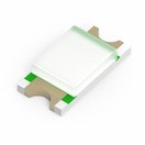 | 150120RS75000 | SPEC | 7 Dateien | Aktiv i| Produktion ist aktiv. Erwartete Lebenszeit: >10 Jahre. | WL-SMCW SMT Mono-color Chip LED Waterclear | 625 | Rot | 630 | 150 | 2 | AlInGaP | 140 | – | – | 1206 | -40 °C up to +85 °C | – | – | – | – | 3.2 | 1.6 | 0.68 | – | Tape and Reel | – | – | – | – | SMT | – | – | – | – | – | – | – | – | – | – | – | – | – | – | – | – | ||
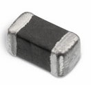 | 742792651 | SPEC | 9 Dateien | Aktiv i| Produktion ist aktiv. Erwartete Lebenszeit: >10 Jahre. | WE-CBF SMT-Ferrit | – | – | – | – | – | – | – | – | – | 0603 | -55 °C up to +125 °C | – | – | – | – | 1.6 | 0.8 | 0.8 | 0.3 | – | – | – | – | – | SMT | 1000 | – | – | – | 600 | 800 | 200 MHz | 1000 | 0.2 | Hochstrom | – | – | 800 | – | – | – | ||
 | 744232090 | SPEC | 10 Dateien | Aktiv i| Produktion ist aktiv. Erwartete Lebenszeit: >10 Jahre. | WE-CNSW Stromkompensierter SMT Line Filter | – | – | – | – | – | – | – | – | – | 1206 | -40 °C up to +125 °C | – | – | – | – | 3.2 | 1.6 | 1.8 | – | – | – | – | – | 4 | SMT | – | – | – | – | 90 | – | – | – | 0.3 | – | bifilar | 0.111 | 370 | 50 | 125 | USB 2.0 | ||
| 885012005025 | SPEC | 9 Dateien | Aktiv i| Produktion ist aktiv. Erwartete Lebenszeit: >10 Jahre. | WCAP-CSGP MLCCs 16 V(DC) | – | – | – | – | – | – | – | 10 pF | ±5% | 0402 | -55 °C up to +125 °C | 600 | – | 10 GΩ | NP0 Klasse I | 1 | 0.5 | 0.5 | 0.25 | 7" Tape & Reel | – | – | – | – | – | – | – | – | – | – | – | – | – | – | – | – | – | – | 16 | – | – | |||
| 885012005043 | SPEC | 9 Dateien | Aktiv i| Produktion ist aktiv. Erwartete Lebenszeit: >10 Jahre. | WCAP-CSGP MLCCs 25 V(DC) | – | – | – | – | – | – | – | 33 pF | ±5% | 0402 | -55 °C up to +125 °C | 1000 | – | 10 GΩ | NP0 Klasse I | 1 | 0.5 | 0.5 | 0.25 | 7" Tape & Reel | – | – | – | – | – | – | – | – | – | – | – | – | – | – | – | – | – | – | 25 | – | – | |||
| 885012005056 | SPEC | 9 Dateien | Aktiv i| Produktion ist aktiv. Erwartete Lebenszeit: >10 Jahre. | WCAP-CSGP MLCCs 50 V(DC) | – | – | – | – | – | – | – | 15 pF | ±5% | 0402 | -55 °C up to +125 °C | 700 | – | 10 GΩ | NP0 Klasse I | 1 | 0.5 | 0.5 | 0.25 | 7" Tape & Reel | – | – | – | – | – | – | – | – | – | – | – | – | – | – | – | – | – | – | 50 | – | – | |||
| 885012205027 | SPEC | 9 Dateien | Aktiv i| Produktion ist aktiv. Erwartete Lebenszeit: >10 Jahre. | WCAP-CSGP MLCCs 16 V(DC) | – | – | – | – | – | – | – | 2.2 nF | ±10% | 0402 | -55 °C up to +125 °C | – | 3.5 | 10 GΩ | X7R Klasse II | 1 | 0.5 | 0.5 | 0.25 | 7" Tape & Reel | – | – | – | – | – | – | – | – | – | – | – | – | – | – | – | – | – | – | 16 | – | – | |||
| 885012205031 | SPEC | 9 Dateien | Aktiv i| Produktion ist aktiv. Erwartete Lebenszeit: >10 Jahre. | WCAP-CSGP MLCCs 16 V(DC) | – | – | – | – | – | – | – | 10 nF | ±10% | 0402 | -55 °C up to +125 °C | – | 3.5 | 10 GΩ | X7R Klasse II | 1 | 0.5 | 0.5 | 0.25 | 7" Tape & Reel | – | – | – | – | – | – | – | – | – | – | – | – | – | – | – | – | – | – | 16 | – | – | |||
| 885012205035 | SPEC | 7 Dateien | Aktiv i| Produktion ist aktiv. Erwartete Lebenszeit: >10 Jahre. | WCAP-CSGP MLCCs 16 V(DC) | – | – | – | – | – | – | – | 47 nF | ±10% | 0402 | -55 °C up to +125 °C | – | 5 | 10 GΩ | X7R Klasse II | 1 | 0.5 | 0.5 | 0.25 | 7" Tape & Reel | – | – | – | – | – | – | – | – | – | – | – | – | – | – | – | – | – | – | 16 | – | – | |||
| 885012205037 | SPEC | 7 Dateien | Aktiv i| Produktion ist aktiv. Erwartete Lebenszeit: >10 Jahre. | WCAP-CSGP MLCCs 16 V(DC) | – | – | – | – | – | – | – | 100 nF | ±10% | 0402 | -55 °C up to +125 °C | – | 5 | 5 GΩ | X7R Klasse II | 1 | 0.5 | 0.5 | 0.25 | 7" Tape & Reel | – | – | – | – | – | – | – | – | – | – | – | – | – | – | – | – | – | – | 16 | – | – | |||
| 885012206046 | SPEC | 9 Dateien | Aktiv i| Produktion ist aktiv. Erwartete Lebenszeit: >10 Jahre. | WCAP-CSGP MLCCs 16 V(DC) | – | – | – | – | – | – | – | 100 nF | ±10% | 0603 | -55 °C up to +125 °C | – | 3.5 | 5 GΩ | X7R Klasse II | 1.6 | 0.8 | 0.8 | 0.4 | 7" Tape & Reel | – | – | – | – | – | – | – | – | – | – | – | – | – | – | – | – | – | – | 16 | – | – | |||
| 885012206048 | SPEC | 9 Dateien | Aktiv i| Produktion ist aktiv. Erwartete Lebenszeit: >10 Jahre. | WCAP-CSGP MLCCs 16 V(DC) | – | – | – | – | – | – | – | 220 nF | ±10% | 0603 | -55 °C up to +125 °C | – | 5 | 2.3 GΩ | X7R Klasse II | 1.6 | 0.8 | 0.8 | 0.4 | 7" Tape & Reel | – | – | – | – | – | – | – | – | – | – | – | – | – | – | – | – | – | – | 16 | – | – | |||
| 885012206050 | SPEC | 9 Dateien | Aktiv i| Produktion ist aktiv. Erwartete Lebenszeit: >10 Jahre. | WCAP-CSGP MLCCs 16 V(DC) | – | – | – | – | – | – | – | 470 nF | ±10% | 0603 | -55 °C up to +125 °C | – | 5 | 1.1 GΩ | X7R Klasse II | 1.6 | 0.8 | 0.8 | 0.4 | 7" Tape & Reel | – | – | – | – | – | – | – | – | – | – | – | – | – | – | – | – | – | – | 16 | – | – | |||
| 885012206051 | SPEC | 9 Dateien | Aktiv i| Produktion ist aktiv. Erwartete Lebenszeit: >10 Jahre. | WCAP-CSGP MLCCs 16 V(DC) | – | – | – | – | – | – | – | 680 nF | ±10% | 0603 | -55 °C up to +125 °C | – | 10 | 0.7 GΩ | X7R Klasse II | 1.6 | 0.8 | 0.8 | 0.4 | 7" Tape & Reel | – | – | – | – | – | – | – | – | – | – | – | – | – | – | – | – | – | – | 16 | – | – | |||
| 885012206052 | SPEC | 9 Dateien | Aktiv i| Produktion ist aktiv. Erwartete Lebenszeit: >10 Jahre. | WCAP-CSGP MLCCs 16 V(DC) | – | – | – | – | – | – | – | 1 µF | ±10% | 0603 | -55 °C up to +125 °C | – | 10 | 0.1 GΩ | X7R Klasse II | 1.6 | 0.8 | 0.8 | 0.4 | 7" Tape & Reel | – | – | – | – | – | – | – | – | – | – | – | – | – | – | – | – | – | – | 16 | – | – | |||
| 885012207025 | SPEC | 9 Dateien | Aktiv i| Produktion ist aktiv. Erwartete Lebenszeit: >10 Jahre. | WCAP-CSGP MLCCs 10 V(DC) | – | – | – | – | – | – | – | 4.7 µF | ±10% | 0805 | -55 °C up to +125 °C | – | 10 | 0.02 GΩ | X7R Klasse II | 2 | 1.25 | 1.25 | 0.5 | 7" Tape & Reel | – | – | – | – | – | – | – | – | – | – | – | – | – | – | – | – | – | – | 10 | – | – | |||
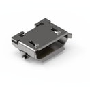 | 629105136821 | SPEC | – | 6 Dateien | Aktiv i| Produktion ist aktiv. Erwartete Lebenszeit: >10 Jahre. | WR-USB Mini/Micro Connectors | – | – | – | – | – | – | – | – | – | – | -40 °C up to +105 °C | – | – | 1000 MΩ | – | – | – | – | – | Tape and Reel | Type B | Mit Pads & Pegs | Buchse | 5 | SMT | 1000 | 30 | – | – | – | – | – | – | – | Horizontal | – | – | 1000 | – | – | Micro USB 2.0 | |
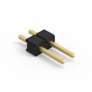 | 61300211121 | SPEC | – | 7 Dateien | Aktiv i| Produktion ist aktiv. Erwartete Lebenszeit: >10 Jahre. | WR-PHD Pin Header - Single | – | – | – | – | – | – | – | – | – | – | -40 °C up to +105 °C | – | – | 1000 MΩ | – | 5.08 | – | – | – | Beutel | – | – | Stiftleiste | 2 | THT | – | 250 | 2.54 | Single | – | – | – | – | – | Gerade | – | – | 3000 | – | – | – | |
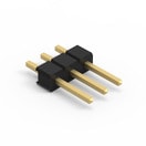 | 61300311121 | SPEC | – | 7 Dateien | Aktiv i| Produktion ist aktiv. Erwartete Lebenszeit: >10 Jahre. | WR-PHD Pin Header - Single | – | – | – | – | – | – | – | – | – | – | -40 °C up to +105 °C | – | – | 1000 MΩ | – | 7.62 | – | – | – | Beutel | – | – | Stiftleiste | 3 | THT | – | 250 | 2.54 | Single | – | – | – | – | – | Gerade | – | – | 3000 | – | – | – |
| Muster |
|---|
| Artikel Nr. | Datenblatt | Simulation | Downloads | Status | Produktserie | λDom typ. (nm) | Farbe | λPeak typ. (nm) | IV typ. (mcd) | VF typ. (V) | Chiptechnologie | 2θ50% typ. (°) | C | Tol. C | Bauform | Betriebstemperatur | Q (%) | DF (%) | RISO | Keramiktyp | L (mm) | W (mm) | H (mm) | Fl (mm) | Verpackung | Interface typ | Ausführung | Gender | Pins (pcs) | Montageart | IR 1 (mA) | Arbeitsspannung (V (AC)) | Raster (mm) | Reihen | Z @ 100 MHz (Ω) | Zmax (Ω) | Testbedingung Zmax | IR 2 (mA) | RDC max. (Ω) | Typ | Wicklungstyp | L (µH) | IR (mA) | VR (V) | VT (V (DC)) | Anwendung | Muster |
|---|


