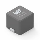
Details
| Topologie | Aufwärtswandler |
| Eingangsspannung | 5.86-40 V |
| Ausgang 1 | 75 V / 1 A |
Beschreibung
The TPS92602-Q1 is a dual-channel LED driver. The basis for each independent driver is a peak-currentmodeboost controller. Each controller has a current feedback loop with high-side current-sensing shuntand a voltage-feedback loop with an external resistor-divider network. Each controller has twoindependent feedback loops, a current-feedback loop with high-side current-sensing shunt and a voltagefeedbackloop with an external resistor-divider network. The controller delivers a constant output voltageor a constant output current. The connected load determines whether the board is regulating a constantoutput current (if current set point is reached earlier than voltage set point) or a constant output voltage (ifthe voltage set point is reached first, for example in an open-load condition).Each controller supports all typical topologies like boost, boost to battery, SEPIC, or flyback.Uses for the high-side PMOS FET driver are for PWM dimming of the LED string and for cutoff in case ofan external short circuit to GND in order to protect the circuit.
Eigenschaften
1.3.1 Connector DescriptionThis section describes the connectors, jumpers, and test points on the EVM and how to properly connect,set up, and use the TPS92602EVM.1.3.2 J_VBAT1, J_VBAT2J_VBAT1 is the CH1 input and J_VBAT2 is the CH2 input.1.3.3 J-PGNDJ_PGND is a common GND for the input.1.3.4 J_B1_OUT, J_B2_OUTJ_B1_OUT is the output of CH1; connect LED+ to this connector. J_B2_OUT is output of CH2; connectLED+ to this connector.1.3.5 J_B1_GND, J_B2_GNDJ_B1_GND is the output GND of CH1; connect LED– to this connector. J_B2_OUT is the output GND ofCH2; connect LED– to this connector.1.3.6 CN1, CN3CN1 is the PWM input for CH1 and CN3 is the PWM input for CH2.1.3.7 CN2, CN4CN2 is the output of DIAG1 and CN4 is the output of DIAG2
Weiterführende Informationen
Artikeldaten
| Artikel Nr. | Datenblatt | Simulation | Downloads | Status | Produktserie | L (µH) | IRP,40K (A) | ISAT,10% (A) | ISAT,30% (A) | RDC max. (mΩ) | Material | LR (µH) | fres (MHz) | Muster | |
|---|---|---|---|---|---|---|---|---|---|---|---|---|---|---|---|
 | 7443321000 | SPEC | 9 Dateien | Aktiv i| Produktion ist aktiv. Erwartete Lebenszeit: >10 Jahre. | WE-HCC SMT-Hochstrominduktivität | 10 | 9.6 | 9.1 | 11.3 | 16.7 | Ferrite | 7.5 | 29 |
| Artikel Nr. | Datenblatt | Simulation | |
|---|---|---|---|
 | 7443321000 | SPEC |
| Muster |
|---|
| Artikel Nr. | Datenblatt | Simulation | Downloads | Status | Produktserie | L (µH) | IRP,40K (A) | ISAT,10% (A) | ISAT,30% (A) | RDC max. (mΩ) | Material | LR (µH) | fres (MHz) | Muster |
|---|


