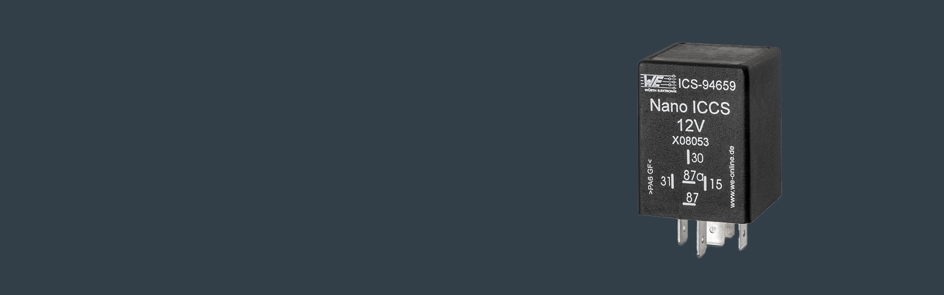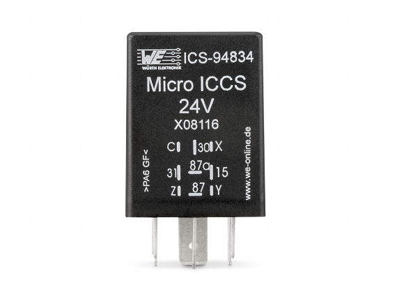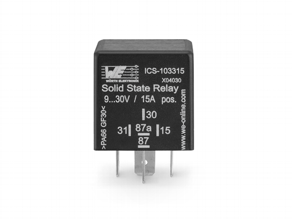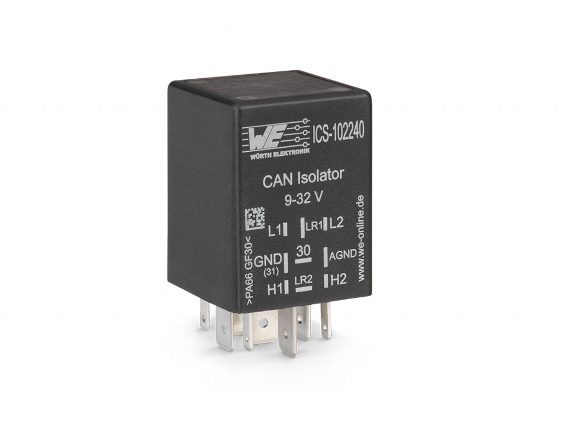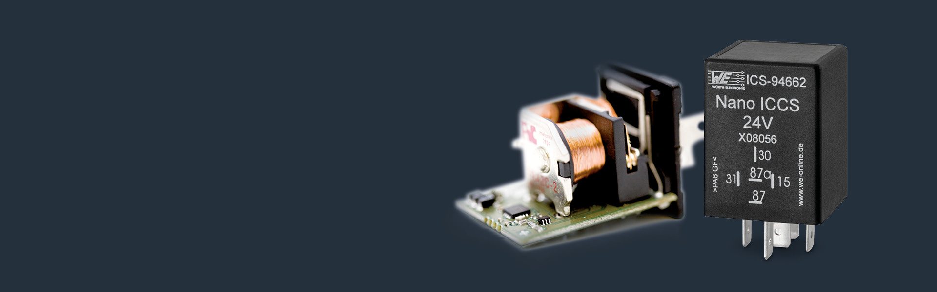
Small Controllers in Relay Design
The small controllers are packaged as relays with 5 or 6 pins and can be connected to the circuit board using standard relay sockets.
Thanks to MSP430 16 Bit microcontroller with flash memory, you can control functions which can be created with a digital input and relay change over contact, such as
|
Operating temperature |
-40 °C to +85 °C |
|---|---|
|
Operating voltage |
12 V or 24 V version |
|
Continuous current |
20/30 A (NC/NO) |
|
Breaking current max |
60 A |
|
Quiescent current |
<1 mA |
|
Ingress protection |
IP 53 IP 65 with IP socket |
|
e1 approval-no. |
03 5688 |
|
Dimensions |
40 x 30 x 30 cm |
|
|
S1 |
S2 |
S3 |
|---|---|---|---|
|
Electronics' power |
linked |
standalone |
linked |
|
Main power |
linked |
standalone |
standalone |
|
Digital input |
standalone |
standalone |
linked |
|
Description |
VCC |
Order number WE ICS |
|---|---|---|
|
Nano ICCS 12 V S1 |
VCC pin 30 |
ICS-94659 |
|
Nano ICCS 12 V S1 NEG |
VCC pin 30 |
ICS-100642 |
|
Nano ICCS 12 V S2 |
VCC pin 30 |
ICS-94660 |
|
Nano ICCS 12 V S2 NEG |
VCC pin 30 |
ICS-100643 |
|
Nano ICCS 12 V S3 |
VCC pin 15 |
ICS-94661 |
|
Nano ICCS 24 V S1 |
VCC pin 30 |
ICS-94662 |
|
Nano ICCS 24 V S1 NEG |
VCC pin 30 |
ICS-100644 |
|
Nano ICCS 24 V S2 |
VCC pin 30 |
ICS-94663 |
|
Nano ICCS 24 V S2 NEG |
VCC pin 30 |
ICS-100645 |
|
Nano ICCS 24 V S3 |
VCC pin 15 |
ICS-94664 |
Nano ICCS
Tell us your requirements and receive a proposal including a placement suggestion within the shortest possible time.
You determine the delay time - Nano ICCS Time Relay - Switch Off Delay - are used to switch off a load precisely after a given time.
The supply voltage is applied to terminal 30. As soon as signal voltage is applied to terminal 15, the relay switches on immediately. If signal voltage is removed from terminal 15, the relay switches off after the defined delay time.
Matching circuit diagrams: S1 and S2
Application examples
You determine the delay time, the Nano ICCS Time Relay - Switch-On Delay - switches consumers on precisely.
The supply voltage is applied to terminal 30 (on the diagram S3 to terminal 87z). As soon as signal voltage is applied to terminal 15, the relay switches on after the given delay time has expired. If signal voltage is removed from terminal 15, the relay switches-off immediately.
Matching circuit diagrams: S1, S2 and S3
Application Examples:
Nano ICCS Time Relay – Switch-On and Switch-Off Delay – are used to switch on or off a load after a given time.
The supply voltage is applied to terminal 30. As soon as signal voltage is applied to terminal 15, the relay switches on after the given delay time is expired. When the signal voltage is removed from terminal 15, the relay switches off after the defined delay time.
Matching circuit diagrams: S1 and S2
Application examples
Nano ICCS Impulse Relays are used to switch loads on and off for an individually defined time period – such as in control devices for preheating times.
The supply voltage is applied to terminal 30 (on the diagram S3 to terminal 87z). If control voltage is applied to terminal 15, the relay switches-on for the given time period and switches-off afterwards.
If you need to switch loads on or off such as e.g. working lights via a button, you can use Nano ICCS Toggle Relays.
If a positive impulse is applied to terminal 15, the relay switches and becomes self-sustained (on or off). One more impulse and it switches again (impulse switch or toggle-flip-flop). Terminal 15 is debounced.
Matching circuit diagrams: S1 and S2
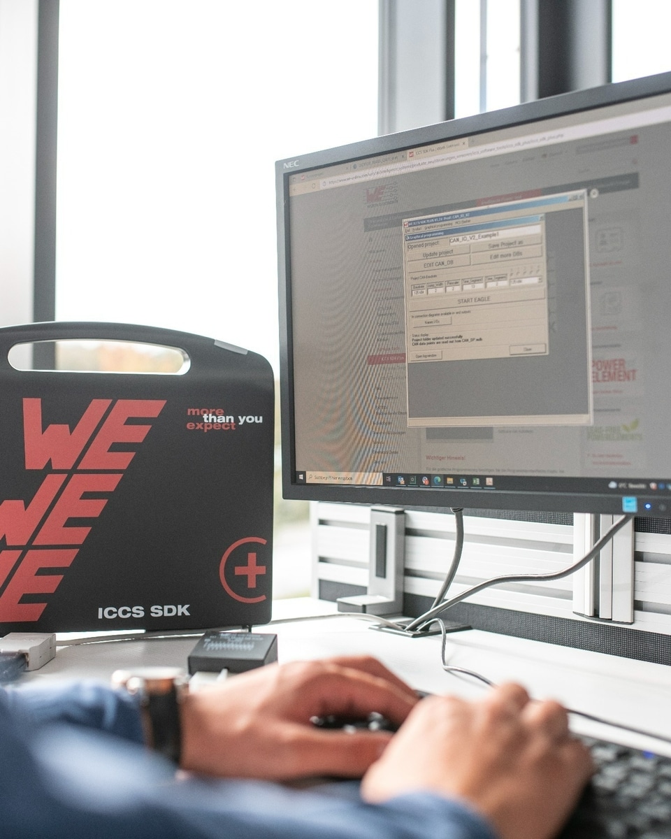
Programming
In the Development Phase, We Are Happy To Support You in the Creation of Programs.
In the Series Phase We Deliver Nano ICCS Already Programmed With the Desired Function.