RIGID.FLEX Physical PCB Sample WE.flexone
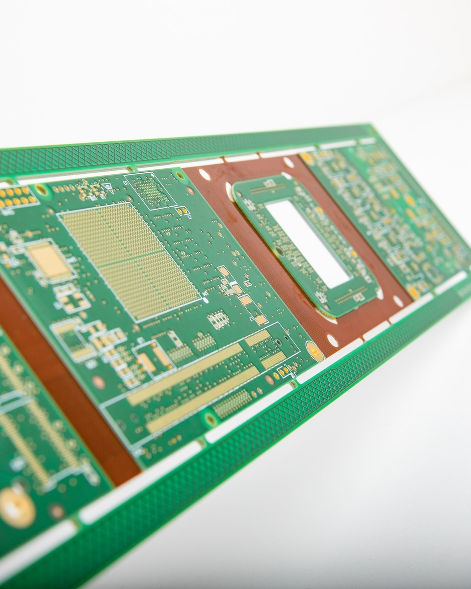
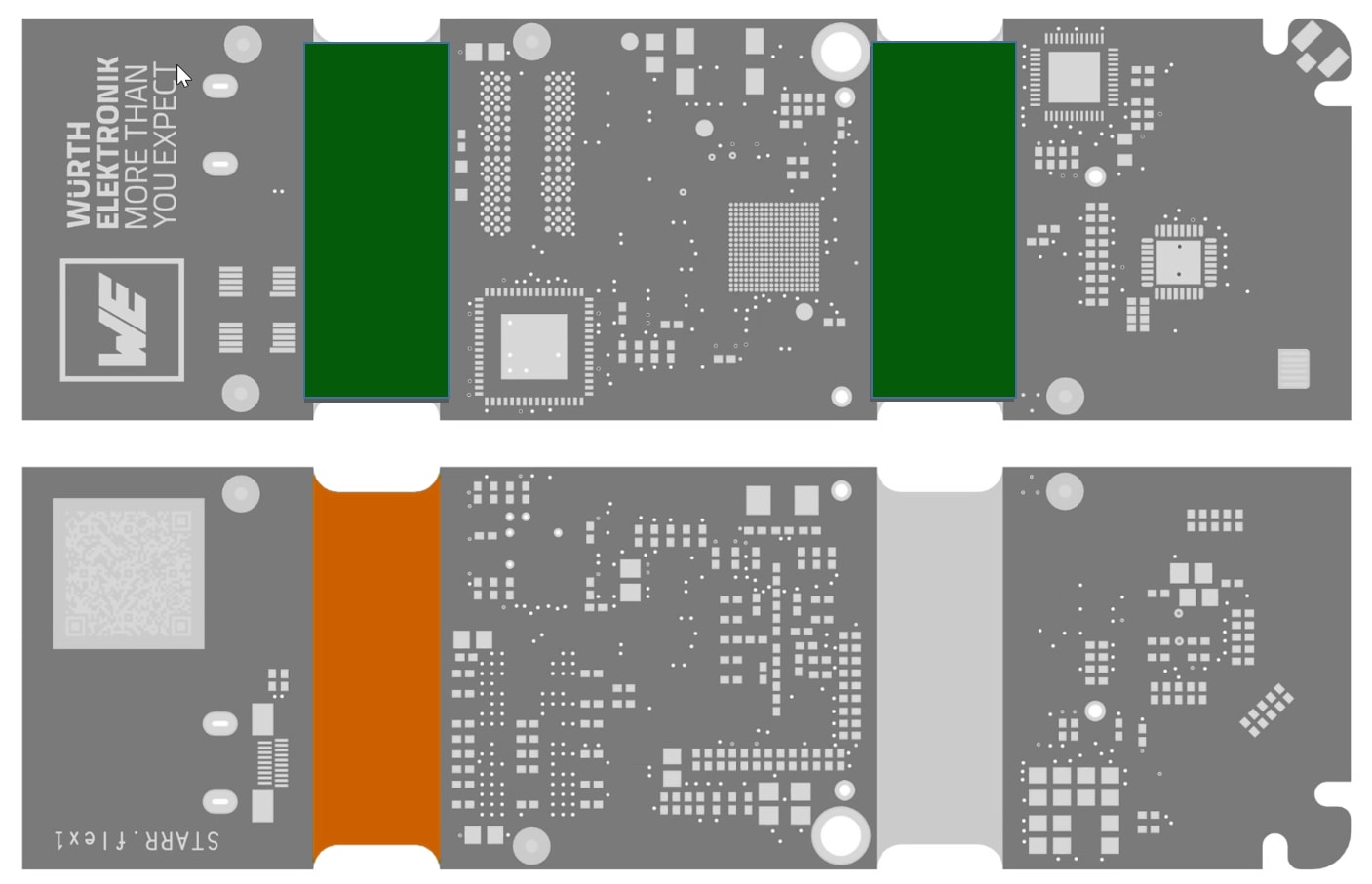
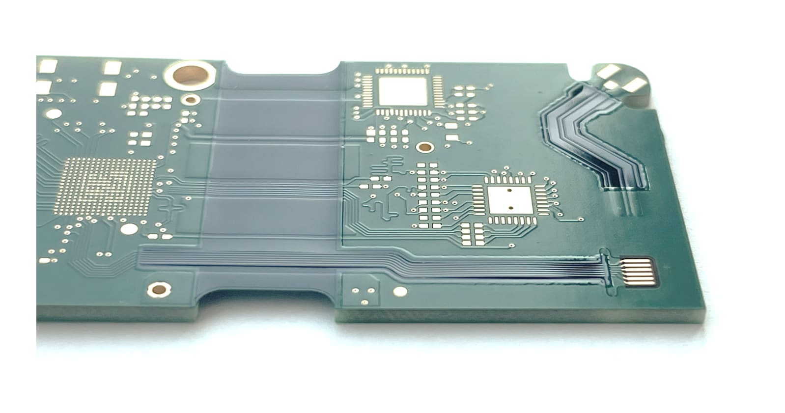
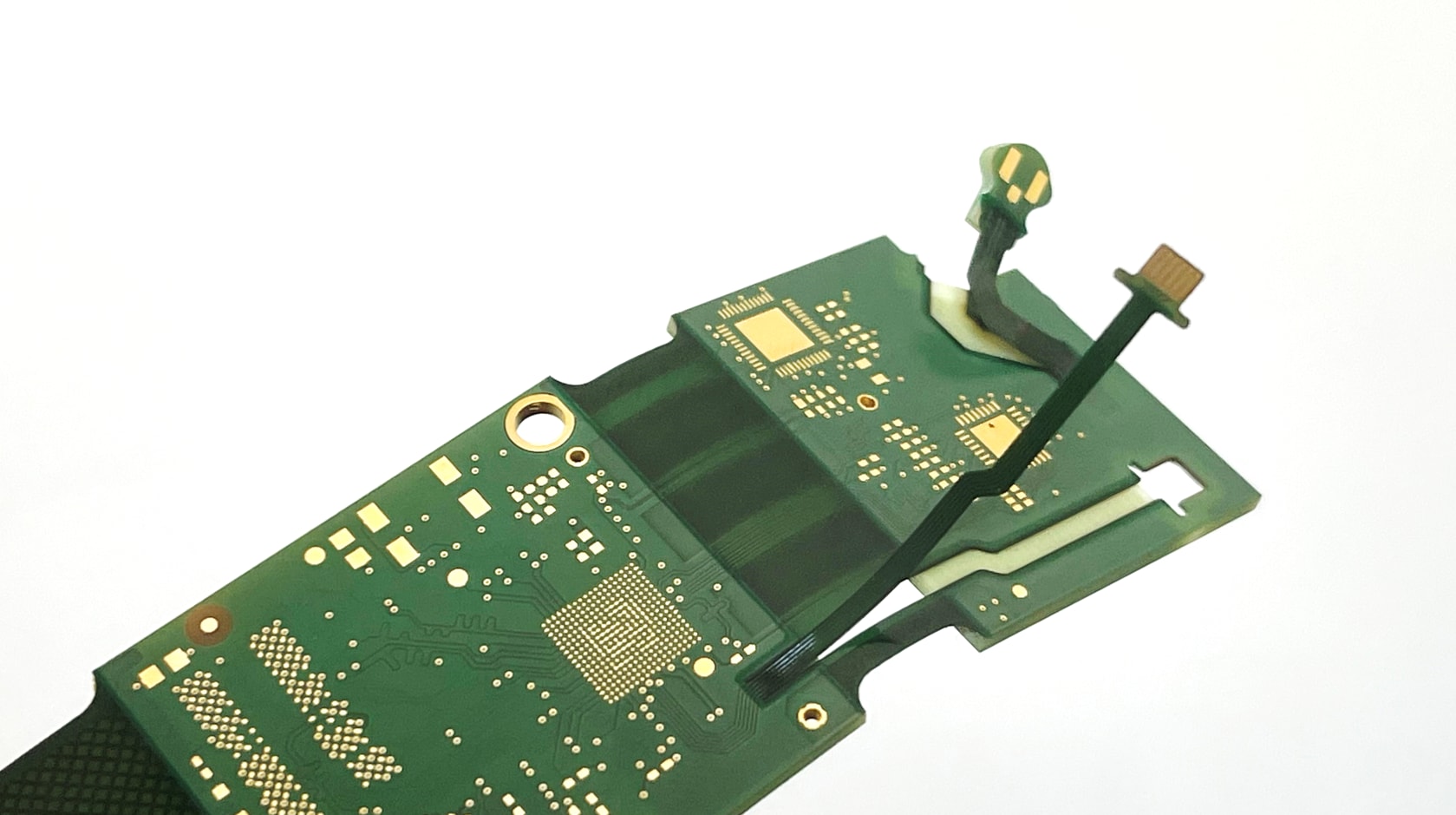
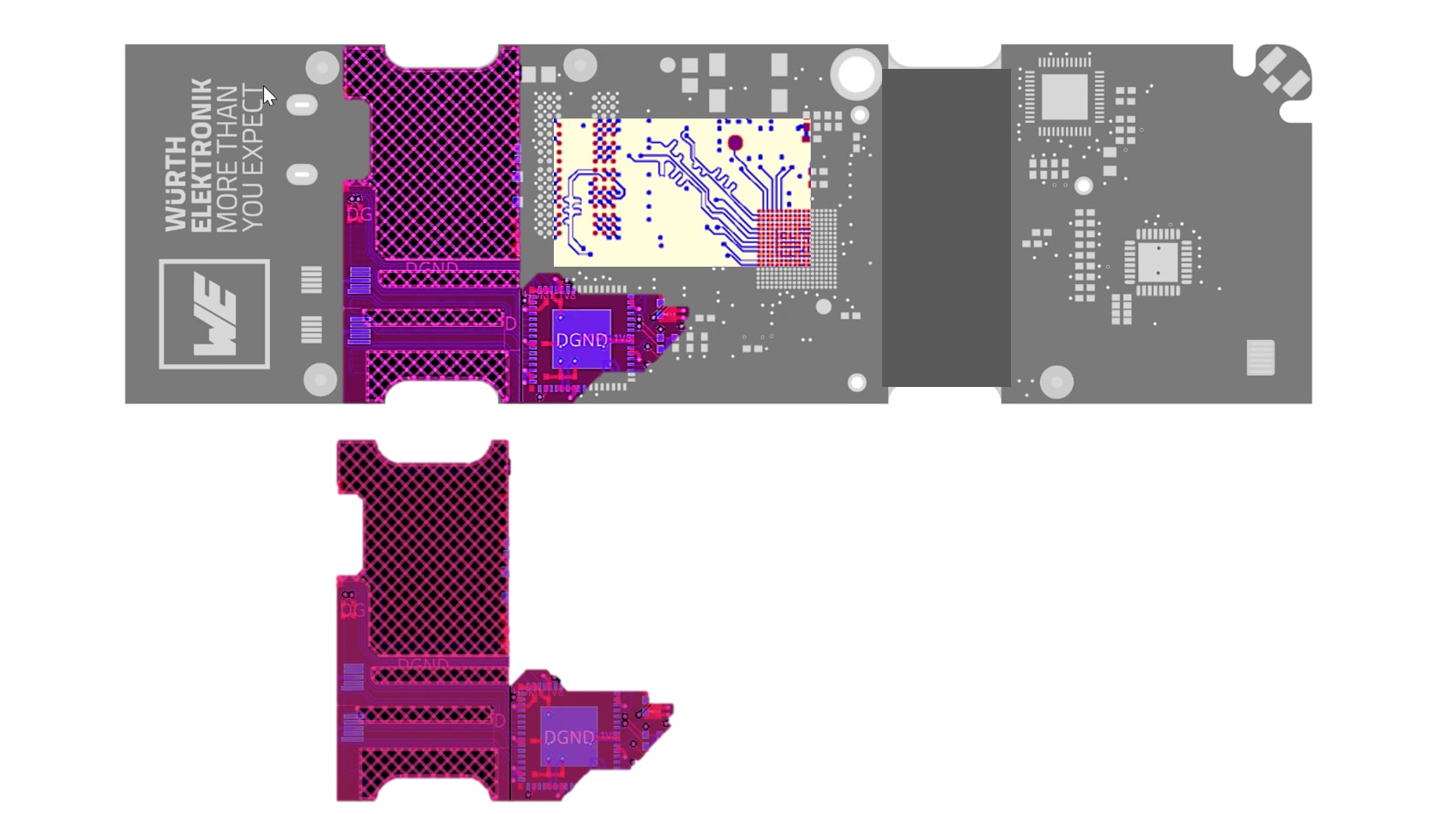
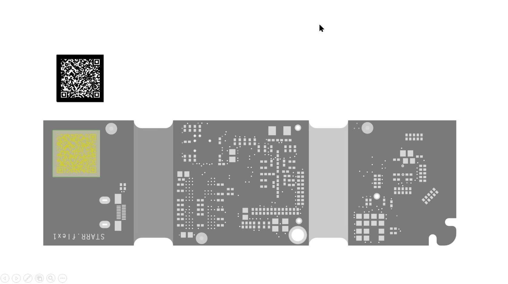
Our RIGID.flex sample WE.flexone shows you the diverse mechatronic possibilities of this PCB technology with external flex layers. Thus, the difference between one and two copper layers in the two flex areas becomes touchable in the literal sense. In addition, the different coatings of the flex areas can be compared with flexible solder resist as well as with Coverlay. The use of Microvias to unbundle a BGA with pitch 0.4 mm is indicated. The sample shows a clever form of the popular ZIF contact and a flexibly tethered high frequency connector. A detachable lift-off area stimulates the senses and can trigger new product ideas.
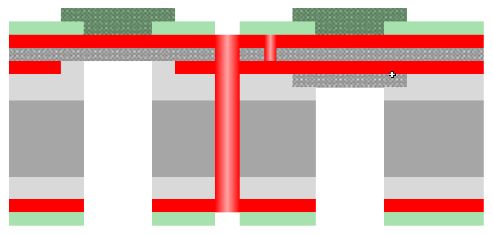
Design: Stackup: RIGID.flex 1F-1Ri & 2F-1Ri
Explanations: Cost-effective design with flex layers on the outside, thus less effort in production compared to flex layers on the inside, especially for a stackup 1F-xRi. The rigid base materials are FR4.1 quality as standard (low halogen, filled, Tg 150°C).
Design: Flexible soldermask and Coverlay
Explanations: The most cost-effective version on outer layers is flexible solder resist, which can be identified by its green color. Coverlay is used for inner flex layers and for higher resistance on outer layers.
Design: The outline of the sample is milled. The contours of the flexible areas are laser cut, in the lift-off areas with micro webs - this allows separation without tools by hand.
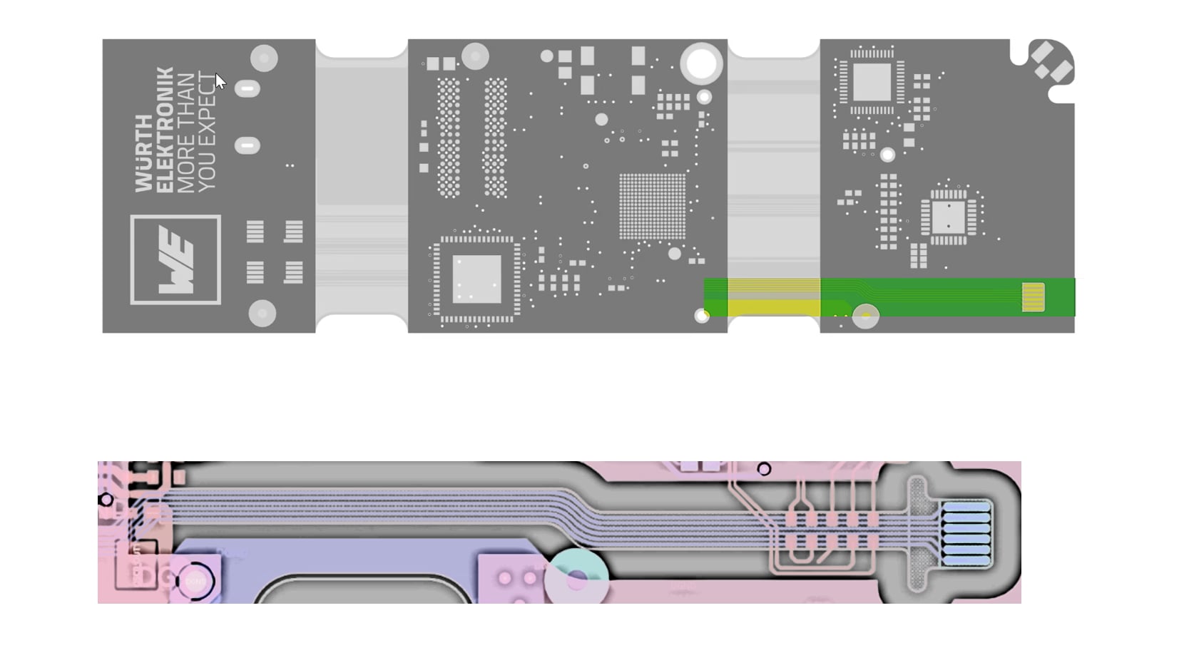
Design: Both flex areas are 10 mm long. The sample can be bent up to 180° in U- or S-shape and contains electrical interfaces in the form of coaxial connectors and ZIF contacts, which can be connected with long flex tails and thus flexibly and mechanically decoupled fastened or connected in a housing.
Design: Design in 2F zone with reference layer possible. Specified impedances with project-specific stackup, length compensation for runtime matching
Explanations: Critical signals between components without layer changes over the flex area, Hatch structures outside the critical signal areas for higher flexibility and faster drying.
Design: The ZIF contact with a thickness of 0.3 mm ± 0.05 mm is formed from the rigid area by a deep milling process. The flexible lead can be lifted off the rigid area as a so-called lift-off area without further tools. The entire contour is cut with a laser and has micro webs that can be separated by hand without damaging the flex area.
Explanations: ZIF = Zero Insertion Force
Explanations: Content includes link to https://www.we-online.com/we.flexone

