Analog Devices LT8612 | Demoboard DC2010A
DC2010A - LT8612 Demo Circuit | 5.8V ≤ VIN ≤ 42V, Vout = 5V @ 6A
Details
| Topologie | Abwärtswandler |
| Eingangsspannung | 5.8-42 V |
| Schaltfrequenz | 665-735 kHz |
| Ausgang 1 | 5 V / 6 A |
| IC-Revision | 3 |
Beschreibung
Demonstration circuit 2010A is a 42V, 6A micropower synchronous step-down regulator featuring the LT®8612. The demo board is designed for 5V output from a 5.8V to 42V input. The wide input range allows a variety ofinput sources, such as automotive batteries and industrial supplies. The LT8612 is a compact, high efficiency, and high speed synchronous monolithic step-down switching regulator. The integrated power switches and inclusion of all necessary circuitry reduce the components countand solution size. Ultralow 3μA quiescent current in Burst Mode® operation achieves high efficiency at very light loads. Fast minimum on-time of 40ns enables high VIN to low VOUT conversion at high frequency.The LT8612 switching frequency can be programmed either via oscillator resistor or external clock over a 200kHz to 2.2MHz range. The SYNC pin on the demo board is grounded by default for low ripple burst mode operation.To synchronize to an external clock, move JP1 to SYNC and apply the external clock to the SYNC turret. Once JP1 is on SYNC position, a DC voltage of 3V or higher can be applied to the SYNC turret for pulse-skipping operation.Demonstration circuit 2010A is a 42V, 6A micropower synchronous step-down regulator featuring the LT®8612.The demo board is designed for 5V output from a 5.8V to 42V input. The wide input range allows a variety of input sources, such as automotive batteries and industrial supplies. The LT8612 is a compact, high efficiency, and high speed synchronous monolithic step-down switching regulator. The integrated power switches and inclusion of all necessary circuitry reduce the components count and solution size. Ultralow 3μA quiescent current in Burst Mode® operation achieves high efficiency at very light loads. Fast minimum on-time of 40ns enables high VIN to low VOUT conversion at high frequency.The LT8612 switching frequency can be programmed either via oscillator resistor or external clock over a 200kHz to 2.2MHz range. The SYNC pin on the demo board is grounded by default for low ripple burst mode operation. To synchronize to an external clock, move JP1 to SYNCand apply the external clock to the SYNC turret. Once JP1 is on SYNC position, a DC voltage of 3V or higher can be applied to the SYNC turret for pulse-skipping operation.
Eigenschaften
Remarks:L1=3.3uH,L3=6.8uHrefer page no.4
Weiterführende Informationen
Artikeldaten
| Artikel Nr. | Datenblatt | Simulation | Downloads | Status | Produktserie | Z @ 100 MHz (Ω) | Zmax (Ω) | Testbedingung Zmax | IR (mA) | Z @ 1 GHz (Ω) | H (mm) | Typ | Muster | |
|---|---|---|---|---|---|---|---|---|---|---|---|---|---|---|
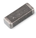
 | 74279226101 | SPEC | 10 Dateien | Aktiv i| Produktion ist aktiv. Erwartete Lebenszeit: >10 Jahre. | WE-MPSB EMI Multilayer Power Suppression Bead | 100 | 160 | 1100 MHz | 8000 | 150 | 2.3 | Hochstrom |
| Artikel Nr. | Datenblatt | Simulation | |
|---|---|---|---|
 | 74279226101 | SPEC |
| Muster |
|---|
| Artikel Nr. | Datenblatt | Simulation | Downloads | Status | Produktserie | Z @ 100 MHz (Ω) | Zmax (Ω) | Testbedingung Zmax | IR (mA) | Z @ 1 GHz (Ω) | H (mm) | Typ | Muster |
|---|


