Analog Devices LT8709 | Demoboard DC2148A
LT8709 Negative Input Synchronous Multi-Topology DC/DC Controller
Details
| Topologie | Abwärts- und Aufwärtswandler |
| Eingangsspannung | -4.5 - -38 V |
| Ausgang 1 | -12 V / 5 A |
| IC-Revision | 3 |
Beschreibung
Demonstration circuit 2148A features the LT®8709, a negative input synchronous multi-topology DC/DC controller designed for negative input power supplies where the highest input supply voltage is ground. Examples of these circuits include negative buck, negative boost, negative buck-boost and negative inverting. The DC2148A is a negative buck-boost with an operating input voltage range from –4.5V to –38V and an output voltage of –12V, however this demo circuit can be easily reconfigured for other negative input topologies. The maximum output current for DC2148A is 5A, the switching frequency is 400kHz and the maximum efficiency with a –12V input is 91%.
The output voltage is programmed with a single resistor R7 and a –4.22V turn-on threshold is programmed with resistor divider R3 and R4. Current sense resistor R1 programs the switch current limit and current senseresistor R2 programs an output current limit. Filters can be added to the switch and output current sense resistors using component placeholders on the PCB. The IMON output voltage is proportional to output current and a 0.1μ capacitor C17 filters IMON.
This demo circuit uses logic-level 60V NMOS and PMOS that operate down to a –4.5V input voltage. Diode D1 is in parallel with the PMOS to improve efficiency. Resistors can be added to the gate drives of both NMOS andPMOS. There are placeholders so the NMOS and PMOS can be paralleled.
Ceramic capacitors are used at both the circuit input and output because of their small size and high ripple current capability. The input has an aluminum electrolytic capacitor in addition to the ceramic capacitors and there is a placeholder to add an electrolytic capacitor at the output.
The MODE input is pulled up to INTVCC by 100k resistor R14 which allows discontinuous conduction mode (DCM) and pulse-skipping operation. There is a placeholder that can be used to connect MODE to –VIN instead of INTVCC for continuous conduction mode (CCM) switching.
The switching frequency is adjustable using resistor R5. The SYNC input can be used to synchronize the switching frequency. Zero ohm jumper R16 from SYNC to –VIN must be removed prior to using the SYNC input. Feedbackloop compensation can be optimized using componentR6, C7 and C8.Capacitor C14 at the SS pin programs soft-start. PG is an open-collector status flag output and is pulled up to the INTVCC pin voltage by the 100k resistor R23.
There are placeholders to add level shifting circuitry for EN/FBIN, SYNC and PG signals. In addition, the demo circuit is designed to be easily reconfigured to many other applications, including the example schematics in the data sheet. The PCB has extensive vias for thermal performance.
Synchronous switching and negative input operation make the LT8709 attractive for negative input, high-power voltage regulator circuits. The LT8709EFE is available in a thermally enhanced 20-lead TSSOP package. The LT8709 data sheet must be read in conjunction with this demo manual to properly use or modify DC2148A
Weiterführende Informationen
Artikeldaten
| Artikel Nr. | Datenblatt | Simulation | Downloads | Status | Produktserie | L1 (µH) | L2 (µH) | n | IR 1 (A) | IR 2 (A) | ISAT1 (A) | ISAT2 (A) | RDC 1 (mΩ) | RDC 2 (mΩ) | Muster | |
|---|---|---|---|---|---|---|---|---|---|---|---|---|---|---|---|---|
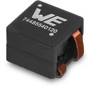
 | 74485540350 | SPEC | 8 Dateien | Aktiv i| Produktion ist aktiv. Erwartete Lebenszeit: >10 Jahre. | WE-CFWI Gekoppelte Flachdraht Doppeldrossel | 3.5 | 3.5 | 1:1 | 14 | 14 | 27 | 27 | 7.5 | 7.5 |
| Artikel Nr. | Datenblatt | Simulation | |
|---|---|---|---|
 | 74485540350 | SPEC |
| Muster |
|---|
| Artikel Nr. | Datenblatt | Simulation | Downloads | Status | Produktserie | L1 (µH) | L2 (µH) | n | IR 1 (A) | IR 2 (A) | ISAT1 (A) | ISAT2 (A) | RDC 1 (mΩ) | RDC 2 (mΩ) | Muster |
|---|


