EPC EPC2007C | Demoboard EPC9507
ZVS Class-D Wireless Power Amplifier Demo Board using EPC2007C / EPC2038
Details
| Topologie | Abwärtswandler |
| Eingangsspannung | 8-36 V |
| Ausgang 1 | 2 V / 6 A |
| IC-Revision | 3.0 |
Beschreibung
The EPC9506 / EPC9507 is a high efficiency, Zero Voltage Switching (ZVS), Class-D Wireless Power amplifier demonstration board operating at 6.78 MHz (Lowest ISM band). The purpose of this demonstration system is to simplify the evaluation process of wireless power technology using eGaN® FETs by including all the critical components on a single board that can be easily connected into an existing system.The amplifier board features the EPC2014 (40 V rated - EPC9506) or EPC2007 (100 V rated – EPC9507) enhancement mode field effect transistor (FET) in an optional half-bridge topology (single ended configuration) or default full-bridge topology (differential configuration), and includes the gate driver/s and oscillator that ensures operation of the system at 6.78 MHz. The source board can also be operated using an external oscillator.The amplifier board is equipped with a pre-regulator that limits the currentof the supply to the amplifier. As the amplifier draws more current, whichcan be due to the absence of a device coil, the pre-regulator will reducethe voltage being supplied to the amplifier that will ensure a safe operatingpoint. The pre-regulator also monitors the temperature of the mainamplifier FETs and will reduce current if the temperature exceeds 85°C.The pre-regulator can be bypassed to allow testing with custom controlhardware. The board further allows easy access to critical measurementnodes that allow accurate power measurement instrumentation hookup.A simplified diagram of the amplifier board is given in Figure 1.For more information on the EPC2014 or EPC2007 eGaN FET please referto the datasheet available from EPC at www.epc-co.com. The data-sheetshould be read in conjunction with this quick start guide
Weiterführende Informationen
Artikeldaten
| Artikel Nr. | Datenblatt | Simulation | Downloads | Status | Produktserie | L (µH) | IRP,40K (A) | ISAT,10% (A) | ISAT,30% (A) | RDC (mΩ) | fres (MHz) | Material | Pins (pcs) | Raster (mm) | Reihen | H (mm) | Gender | Typ | IR (A) | Verpackung | Farbe | Montageart | IR 1 (A) | Arbeitsspannung (V (AC)) | PCB/Kabel/Panel | Kontaktwiderstand (mΩ) | Tol. R | L (mm) | Muster | |
|---|---|---|---|---|---|---|---|---|---|---|---|---|---|---|---|---|---|---|---|---|---|---|---|---|---|---|---|---|---|---|
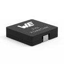 | 744314101 | SPEC | 9 Dateien | Aktiv i| Produktion ist aktiv. Erwartete Lebenszeit: >10 Jahre. | WE-HCI SMT-Hochstrominduktivität | 10 | 5.3 | 1.8 | 4 | 33 | 40 | Superflux | 2 | – | – | 4.8 | – | – | – | – | – | SMT | – | – | – | – | – | 7 | ||
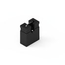 | 60900213421 | SPEC | – | 3 Dateien | Aktiv i| Produktion ist aktiv. Erwartete Lebenszeit: >10 Jahre. | WR-PHD Jumper | – | – | – | – | – | – | – | 1 | 2.54 | – | – | Jumper | – | 3 | Beutel | Schwarz | – | – | 250 | – | 20 | max. | 2.44 | |
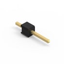 | 61300111121 | SPEC | – | 7 Dateien | Aktiv i| Produktion ist aktiv. Erwartete Lebenszeit: >10 Jahre. | WR-PHD Pin Header - Single | – | – | – | – | – | – | – | 1 | 2.54 | Single | – | Stiftleiste | Gerade | 3 | Beutel | – | THT | – | 250 | – | 20 | max. | 2.54 | |
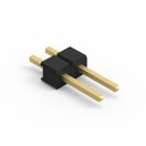 | 61300211121 | SPEC | – | 7 Dateien | Aktiv i| Produktion ist aktiv. Erwartete Lebenszeit: >10 Jahre. | WR-PHD Pin Header - Single | – | – | – | – | – | – | – | 2 | 2.54 | Single | – | Stiftleiste | Gerade | 3 | Beutel | – | THT | – | 250 | – | 20 | max. | 5.08 | |
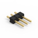 | 61300311121 | SPEC | – | 7 Dateien | Aktiv i| Produktion ist aktiv. Erwartete Lebenszeit: >10 Jahre. | WR-PHD Pin Header - Single | – | – | – | – | – | – | – | 3 | 2.54 | Single | – | Stiftleiste | Gerade | 3 | Beutel | – | THT | – | 250 | – | 20 | max. | 7.62 | |
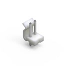 | 645002114822 | SPEC | – | 7 Dateien | Aktiv i| Produktion ist aktiv. Erwartete Lebenszeit: >10 Jahre. | WR-WTB 3.96 mm Male Header | – | – | – | – | – | – | – | 2 | 3.96 | – | – | Männlich | Vertikal | 7 | Beutel | Weiß | THT | 7 | 250 | PCB | 20 | max. | 7.92 |
| Artikel Nr. | Datenblatt | Simulation | |
|---|---|---|---|
 | 744314101 | SPEC | |
 | 60900213421 | SPEC | – |
 | 61300111121 | SPEC | – |
 | 61300211121 | SPEC | – |
 | 61300311121 | SPEC | – |
 | 645002114822 | SPEC | – |
| Muster |
|---|
| Artikel Nr. | Datenblatt | Simulation | Downloads | Status | Produktserie | L (µH) | IRP,40K (A) | ISAT,10% (A) | ISAT,30% (A) | RDC (mΩ) | fres (MHz) | Material | Pins (pcs) | Raster (mm) | Reihen | H (mm) | Gender | Typ | IR (A) | Verpackung | Farbe | Montageart | IR 1 (A) | Arbeitsspannung (V (AC)) | PCB/Kabel/Panel | Kontaktwiderstand (mΩ) | Tol. R | L (mm) | Muster |
|---|


