Details
| Topologie | Sperrwandler |
| Eingangsspannung | 90-264 V |
| Schaltfrequenz | 25-420 kHz |
| Ausgang 1 | 12 V / 3 A |
Beschreibung
This design note describes a 45 watt, Type C interface PD2.0, universal AC input, constant voltage power supply intended for smart phone, PAD and NB adaptor supporting PD2.0 orQC2.0 protocol, where isolation from the AC mains is required, and low cost, high efficiency, and low standby power are essential.The featured power supply is a simple QR flyback topology utilizing ON Semiconductor’s NCP1340B3 HF PWM controller, NCP43080D synchronous rectified controller, NTMFS6B03 synchronous MOSFET and ATP104 Switch MOSFET. This Design Note provides the complete circuit schematic details, PCB and BOM for 45W Type C Interface PD2.0 Power adapter solution which supports PD output (5V/3A, 9V/3A, 12V/3A, 15V/3A, 20V/2.25A).This design combined with CanYon’s CY2211 PD2.0 protocal controller to provide PD2.0 and QC2.0 functions. This design also proposes a dual auxiliary power supply to supply PWMcontroller, the PWM controller is supplied by high voltage auxiliary voltage at low output voltage and supplied by low voltage auxiliary voltage at high output voltage and also shutsdown zener bias of high voltage Vcc while low voltage auxiliary voltage supplies controller.This design also uses synchronous rectified controller to provide high efficiency and also uses an external Vcc pulse regulator to supply synchronous controller to ensure controller can works below 4v.
Eigenschaften
- Universal AC input range (90 – 264 Vac)
- Very low standby (5V & 230Vac) power consumption with no cable plug in
- Very low ripple and noise
- Inherent SCP and OCP protection
- High operation frequency up to 150kHz
- High power density (1.15 W/cm3)
- Quick switching off FET while unplugging cable and switching on FET at Vbus dropping to 5v while plugging cable again
- Quasi-Resonant current mode control with Valley Switching
- Valley lockout avoids audible noise at valley jumping operation
- Support TYPE-C PD2.0&QC2.0 protocol
- Adaptive Output OVP and UVP
- Open loop protection
- Board size: 57mmx36mmx19mm
Typische Anwendungen
- Smart phone, PAD and NB adapter supporting PD2.0 and QC2.0
Weiterführende Informationen
Artikeldaten
| Artikel Nr. | Datenblatt | Simulation | Downloads | Status | Produktserie | Anwendung | C | Sicherheitsklasse | dV/dt (V/µs) | DF @ 1 kHz (%) | RISO | Raster (mm) | Verpackung | ISAT,10% (A) | fres (MHz) | Version | Z @ 100 MHz (Ω) | Zmax (Ω) | Testbedingung Zmax | IR 2 (mA) | RDC max. (Ω) | Typ | IR (mA) | L (mH) | VR (V (AC)) | VT (V (AC)) | Material | L (mm) | W (mm) | H (mm) | Montageart | VRMS (V) | VDC (V) | VBR (V) | IPeak (A) | Wmax (J) | PDiss (W) | VDE-Zulassung | Muster | |
|---|---|---|---|---|---|---|---|---|---|---|---|---|---|---|---|---|---|---|---|---|---|---|---|---|---|---|---|---|---|---|---|---|---|---|---|---|---|---|---|---|
 | 820573011 | SPEC | 7 Dateien | Aktiv i| Produktion ist aktiv. Erwartete Lebenszeit: >10 Jahre. | WE-VD Disk Varistor | 230 VAC | – | – | – | – | – | – | – | – | – | THT | – | – | – | – | – | – | – | – | – | – | – | 9 | 4.1 | 12.5 | THT | 300 | 385 | 470 | 1200 | 35 | 0.25 | Ja | ||
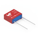
 | 890334022017 | SPEC | 9 Dateien | Aktiv i| Produktion ist aktiv. Erwartete Lebenszeit: >10 Jahre. | WCAP-FTXX Folienkondensatoren | Across the mains | 68 nF | X2 | 400 | 0.1 | 30 GΩ | 7.5 | Lose | – | – | – | – | – | – | – | – | – | – | – | 310 | – | – | 10 | 6 | 12 | Boxed THT | – | – | – | – | – | – | – | ||
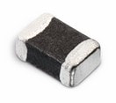
 | 742792040 | SPEC | 9 Dateien | Aktiv i| Produktion ist aktiv. Erwartete Lebenszeit: >10 Jahre. | WE-CBF SMT-Ferrit | – | – | – | – | – | – | – | – | – | – | SMT | 600 | 700 | 150 MHz | 2000 | 0.15 | Hochstrom | 1500 | – | – | – | – | 2 | 1.2 | 0.0009 | SMT | – | – | – | – | – | – | – | ||
 | 742792096 | SPEC | 8 Dateien | Aktiv i| Produktion ist aktiv. Erwartete Lebenszeit: >10 Jahre. | WE-CBF SMT-Ferrit | – | – | – | – | – | – | – | – | – | – | SMT | 1000 | 1000 | 100 MHz | 1000 | 0.3 | Hochstrom | 800 | – | – | – | – | 2 | 1.2 | 0.9 | SMT | – | – | – | – | – | – | – | ||
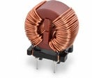
 | 744821110 | SPEC | 11 Dateien | Aktiv i| Produktion ist aktiv. Erwartete Lebenszeit: >10 Jahre. | WE-CMB Stromkompensierte Netzdrossel | – | – | – | – | – | – | – | – | – | – | THT | – | – | – | – | 0.35 | – | 700 | 10 | 250 | 1500 | MnZn | 15 | 7.5 | 18 | THT | – | – | – | – | – | – | 40042670 | ||
 | 7447462470 | SPEC | 9 Dateien | Aktiv i| Produktion ist aktiv. Erwartete Lebenszeit: >10 Jahre. | WE-TI Tonneninduktivität | – | – | – | – | – | – | – | – | 1.2 | 10.6 | Schrumpfschlauch | – | – | – | – | 0.34 | – | 1180 | 0.047 | – | – | NiZn | 6 | 6 | 8.5 | THT | – | – | – | – | – | – | – | ||
 | 750343542 | SPEC | 5 Dateien | Aktiv i| Produktion ist aktiv. Erwartete Lebenszeit: >10 Jahre. | Transformer | – | – | – | – | – | – | – | Tray | – | – | – | – | – | – | – | – | – | – | 0.36 | – | 3000 | – | 21.59 | 21.59 | 17.27 | THT | – | – | – | – | – | – | – |
| Artikel Nr. | Datenblatt | Simulation | |
|---|---|---|---|
 | 820573011 | SPEC | |
 | 890334022017 | SPEC | |
 | 742792040 | SPEC | |
 | 742792096 | SPEC | |
 | 744821110 | SPEC | |
 | 7447462470 | SPEC | |
 | 750343542 | SPEC |
| Muster |
|---|
| Artikel Nr. | Datenblatt | Simulation | Downloads | Status | Produktserie | Anwendung | C | Sicherheitsklasse | dV/dt (V/µs) | DF @ 1 kHz (%) | RISO | Raster (mm) | Verpackung | ISAT,10% (A) | fres (MHz) | Version | Z @ 100 MHz (Ω) | Zmax (Ω) | Testbedingung Zmax | IR 2 (mA) | RDC max. (Ω) | Typ | IR (mA) | L (mH) | VR (V (AC)) | VT (V (AC)) | Material | L (mm) | W (mm) | H (mm) | Montageart | VRMS (V) | VDC (V) | VBR (V) | IPeak (A) | Wmax (J) | PDiss (W) | VDE-Zulassung | Muster |
|---|


