Details
| Topologie | Leistungsfaktor-Korrektur |
| Schaltfrequenz | 120 kHz |
| IC-Revision | 1.1 |
Beschreibung
The compounded LSI of the Power Factor Correction (PFC) converter and Quasi-Resonant (QR) controller type DC/DC converter IC provides an optimum system for all products that include an electrical outlet. BM1C102F has a built in High Voltage starter circuit that tolerates 650V and X-Cap discharge function, and contributes to low power consumption and high speed start. The PFC part operates by Boundary Conduction Mode (BCM). It reduces the switching loss and the switching noise. Because of zero current detection (ZCD) by a resistance, this solution achieves no auxiliary winding and reduces external parts and the bias current. The DC/DC part operates by Quasi-Resonant Mode. This method enables soft switching and helps to keep the EMI low. With putting MOSFET for switching and current detection resistors as external devices, a higher freedom design is possible. This IC has double over voltage protection for the PFC output terminal. IC makes the standby power consumption low by the PFC ON/OFF control function. The IC includes various protect functions such as VCC over voltage protection, external latch protection, brown out protection, soft start function, per-cycle current limiter and over load protection.
Eigenschaften
- PFC+QR Combo IC
- Built-in 650V tolerance start circuit
- VCC pin: under and over voltage protection
- Brown out function
- External latch terminal function
- PFC boundary conduction mode (voltage control)
- PFC Zero Cross Detection
- PFC variable max frequency
- PFC Dynamic & Static OVP function
Typische Anwendungen
- Power Grids
Weiterführende Informationen
Artikeldaten
| Artikel Nr. | Datenblatt | Simulation | Downloads | Status | Produktserie | Pins (pcs) | Anwendung | PCB/Kabel/Panel | Modularity | Typ | Wire Section | C | VR (V (AC)) | VR 2 (V (DC)) | Sicherheitsklasse | dV/dt (V/µs) | DF @ 1 kHz (%) | RISO | Raster (mm) | L (mm) | W (mm) | H (mm) | Verpackung | Tol. C | Bauform | Betriebstemperatur | Q (%) | DF (%) | Keramiktyp | Fl (mm) | Endurance (h) | IRIPPLE (mA) | ILeak (µA) | Ø D (mm) | VRMS (V) | VDC (V) | VBR (V) | IPeak (A) | Wmax (J) | PDiss (W) | VDE-Zulassung | L (µH) | IR (A) | RDC max. (Ω) | Muster | |
|---|---|---|---|---|---|---|---|---|---|---|---|---|---|---|---|---|---|---|---|---|---|---|---|---|---|---|---|---|---|---|---|---|---|---|---|---|---|---|---|---|---|---|---|---|---|---|
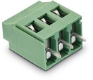 | 691236510002 | SPEC | – | 6 Dateien | Aktiv i| Produktion ist aktiv. Erwartete Lebenszeit: >10 Jahre. | WR-TBL Serie 2365 - 5.08 mm Horiz. Entry w. Rising Cage Clamp | 2 | Käfigzugklemme | PCB | Ja | Horizontal | 12 to 30 (AWG) 3.31 to 0.0509 (mm²) | – | – | – | – | – | – | – | 5.08 | 10.16 | – | – | Karton | – | – | -30 °C up to +120 °C | – | – | – | – | – | – | – | – | – | – | – | – | – | – | – | – | 20 | – | |
 | 691236510003 | SPEC | – | 6 Dateien | Aktiv i| Produktion ist aktiv. Erwartete Lebenszeit: >10 Jahre. | WR-TBL Serie 2365 - 5.08 mm Horiz. Entry w. Rising Cage Clamp | 3 | Käfigzugklemme | PCB | Ja | Horizontal | 12 to 30 (AWG) 3.31 to 0.0509 (mm²) | – | – | – | – | – | – | – | 5.08 | 15.24 | – | – | Karton | – | – | -30 °C up to +120 °C | – | – | – | – | – | – | – | – | – | – | – | – | – | – | – | – | 20 | – | |
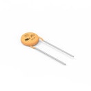 | 820443211E | SPEC | 7 Dateien | Aktiv i| Produktion ist aktiv. Erwartete Lebenszeit: >10 Jahre. | WE-VD Disk Varistor | – | 230 VAC | – | – | – | – | – | – | – | – | – | – | – | – | 16.5 | 4.8 | 20.5 | – | – | 14 mm | -40 °C up to +105 °C | – | – | – | – | – | – | – | 16.5 | 320 | 418 | 510 | 6000 | 190 | 0.6 | Ja | – | – | – | ||
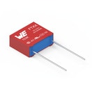 | 890334025027CS | SPEC | 9 Dateien | Aktiv i| Produktion ist aktiv. Erwartete Lebenszeit: >10 Jahre. | WCAP-FTXX Folienkondensatoren | – | Across the mains | – | – | – | – | 220 nF | 310 | 630 | X2 | 180 | 0.1 | 30 GΩ | 15 | 18 | 6 | 11.5 | Karton | ±10% | Raster 15 mm | -40 °C up to +105 °C | – | – | – | – | – | – | – | – | – | – | – | – | – | – | – | – | – | – | ||
 | 7447071 | SPEC | – | 8 Dateien | Aktiv i| Produktion ist aktiv. Erwartete Lebenszeit: >10 Jahre. | WE-FI Funkentstördrossel | – | – | – | – | – | – | – | – | – | – | – | – | – | – | 25 | 13.4 | – | – | – | – | -40 °C up to +105 °C | – | – | – | – | – | – | – | – | – | – | – | – | – | – | – | 470 | 3 | 0.11 | |
 | 860010673012 | SPEC | 8 Dateien | Aktiv i| Produktion ist aktiv. Erwartete Lebenszeit: >10 Jahre. | WCAP-ATG8 Aluminium-Elektrolytkondensatoren | – | – | – | – | – | – | 47 µF | 50 | – | – | – | – | – | 2.5 | 11 | – | – | Ammopack | ±20% | – | – | – | 10 | – | – | 2000 | 165 | 23.5 | 6.3 | – | – | – | – | – | – | – | – | – | – | ||
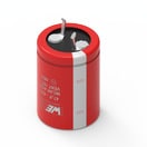 | 861021484017 | SPEC | 8 Dateien | Aktiv i| Produktion ist aktiv. Erwartete Lebenszeit: >10 Jahre. | WCAP-AIG5 Aluminium-Elektrolytkondensatoren | – | – | – | – | – | – | 220 µF | 450 | – | – | – | – | – | 10 | 46 | – | – | Tray | ±20% | 25.0 x 46.0 | -25 °C up to +105 °C | – | 20 | – | – | 2000 | 1240 | 1980 | 25 | – | – | – | – | – | – | – | – | – | – | ||
| 885012007032 | SPEC | 9 Dateien | Aktiv i| Produktion ist aktiv. Erwartete Lebenszeit: >10 Jahre. | WCAP-CSGP MLCCs 25 V(DC) | – | – | – | – | – | – | 47 pF | 25 | – | – | – | – | 10 GΩ | – | 2 | 1.25 | 0.6 | 7" Tape & Reel | ±5% | 0805 | -55 °C up to +125 °C | 1000 | – | NP0 Klasse I | 0.5 | – | – | – | – | – | – | – | – | – | – | – | – | – | – | |||
| 885012207054 | SPEC | 9 Dateien | Aktiv i| Produktion ist aktiv. Erwartete Lebenszeit: >10 Jahre. | WCAP-CSGP MLCCs 25 V(DC) | – | – | – | – | – | – | 100 pF | 25 | – | – | – | – | 10 GΩ | – | 2 | 1.25 | 0.8 | 7" Tape & Reel | ±10% | 0805 | -55 °C up to +125 °C | – | 3.5 | X7R Klasse II | 0.5 | – | – | – | – | – | – | – | – | – | – | – | – | – | – | |||
| 885012207060 | SPEC | 9 Dateien | Aktiv i| Produktion ist aktiv. Erwartete Lebenszeit: >10 Jahre. | WCAP-CSGP MLCCs 25 V(DC) | – | – | – | – | – | – | 1 nF | 25 | – | – | – | – | 10 GΩ | – | 2 | 1.25 | 0.8 | 7" Tape & Reel | ±10% | 0805 | -55 °C up to +125 °C | – | 3.5 | X7R Klasse II | 0.5 | – | – | – | – | – | – | – | – | – | – | – | – | – | – | |||
| 885012207066 | SPEC | 9 Dateien | Aktiv i| Produktion ist aktiv. Erwartete Lebenszeit: >10 Jahre. | WCAP-CSGP MLCCs 25 V(DC) | – | – | – | – | – | – | 10 nF | 25 | – | – | – | – | 10 GΩ | – | 2 | 1.25 | 0.8 | 7" Tape & Reel | ±10% | 0805 | -55 °C up to +125 °C | – | 3.5 | X7R Klasse II | 0.5 | – | – | – | – | – | – | – | – | – | – | – | – | – | – | |||
| 885012207072 | SPEC | 9 Dateien | Aktiv i| Produktion ist aktiv. Erwartete Lebenszeit: >10 Jahre. | WCAP-CSGP MLCCs 25 V(DC) | – | – | – | – | – | – | 100 nF | 25 | – | – | – | – | 5 GΩ | – | 2 | 1.25 | 0.8 | 7" Tape & Reel | ±10% | 0805 | -55 °C up to +125 °C | – | 3.5 | X7R Klasse II | 0.5 | – | – | – | – | – | – | – | – | – | – | – | – | – | – | |||
| 885012207078 | SPEC | 8 Dateien | Aktiv i| Produktion ist aktiv. Erwartete Lebenszeit: >10 Jahre. | WCAP-CSGP MLCCs 25 V(DC) | – | – | – | – | – | – | 1 µF | 25 | – | – | – | – | 0.5 GΩ | – | 2 | 1.25 | 1.25 | 7" Tape & Reel | ±10% | 0805 | -55 °C up to +125 °C | – | 5 | X7R Klasse II | 0.5 | – | – | – | – | – | – | – | – | – | – | – | – | – | – | |||
| 885012207079 | SPEC | 8 Dateien | Aktiv i| Produktion ist aktiv. Erwartete Lebenszeit: >10 Jahre. | WCAP-CSGP MLCCs 25 V(DC) | – | – | – | – | – | – | 2.2 µF | 25 | – | – | – | – | 0.05 GΩ | – | 2 | 1.25 | 1.25 | 7" Tape & Reel | ±10% | 0805 | -55 °C up to +125 °C | – | 10 | X7R Klasse II | 0.5 | – | – | – | – | – | – | – | – | – | – | – | – | – | – | |||
| 885012208048 | SPEC | 9 Dateien | Aktiv i| Produktion ist aktiv. Erwartete Lebenszeit: >10 Jahre. | WCAP-CSGP MLCCs 25 V(DC) | – | – | – | – | – | – | 2.2 nF | 25 | – | – | – | – | 10 GΩ | – | 3.2 | 1.6 | 0.8 | 7" Tape & Reel | ±10% | 1206 | -55 °C up to +125 °C | – | 3.5 | X7R Klasse II | 0.6 | – | – | – | – | – | – | – | – | – | – | – | – | – | – | |||
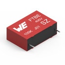 | 890303425004CS | SPEC | 9 Dateien | Aktiv i| Produktion ist aktiv. Erwartete Lebenszeit: >10 Jahre. | WCAP-FTBE Folienkondensatoren | – | – | – | – | – | – | 100 nF | 630 | – | – | 28 | 1 | 9000 MΩ | 15 | 18 | 6 | 12 | Karton | ±10% | Raster 15 mm | – | – | – | – | – | – | – | – | – | – | – | – | – | – | – | – | – | – | – |
| Muster |
|---|
| Artikel Nr. | Datenblatt | Simulation | Downloads | Status | Produktserie | Pins (pcs) | Anwendung | PCB/Kabel/Panel | Modularity | Typ | Wire Section | C | VR (V (AC)) | VR 2 (V (DC)) | Sicherheitsklasse | dV/dt (V/µs) | DF @ 1 kHz (%) | RISO | Raster (mm) | L (mm) | W (mm) | H (mm) | Verpackung | Tol. C | Bauform | Betriebstemperatur | Q (%) | DF (%) | Keramiktyp | Fl (mm) | Endurance (h) | IRIPPLE (mA) | ILeak (µA) | Ø D (mm) | VRMS (V) | VDC (V) | VBR (V) | IPeak (A) | Wmax (J) | PDiss (W) | VDE-Zulassung | L (µH) | IR (A) | RDC max. (Ω) | Muster |
|---|


