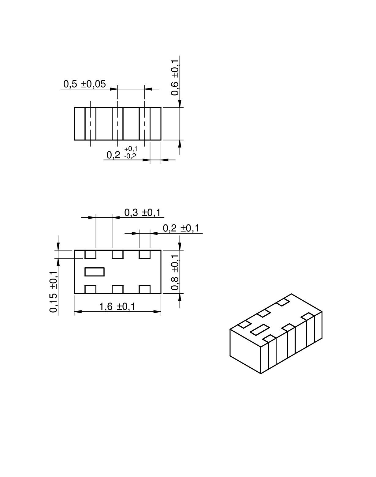
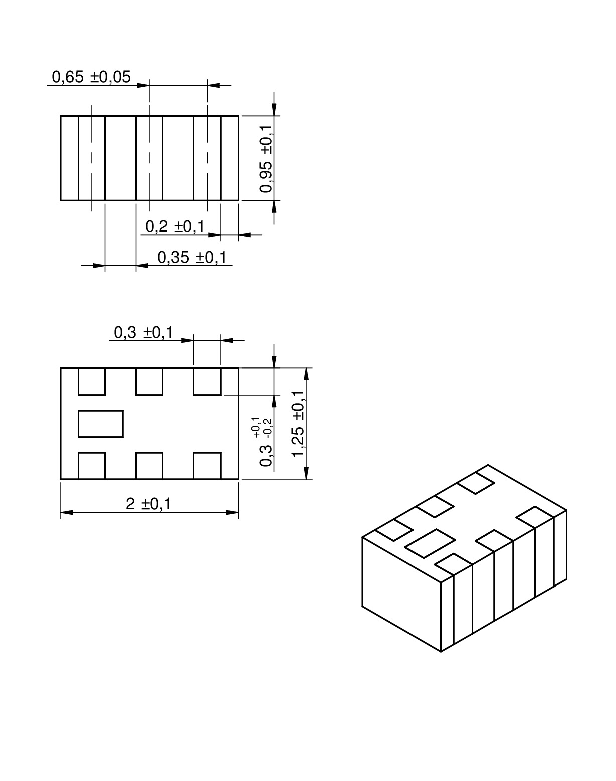
| Size | Dimensions | L (mm) | W (mm) | H (mm) | Mount | ||
|---|---|---|---|---|---|---|---|
| EXT. | 0603 | 1.6 | 0.8 | 0.8 | SMT | ||
| EXT. | 0805 | 2 | 1.25 | 1 | SMT |
LTSpice files
Characteristics
- Low loss SMT Balun with balanced impedance of 50 to 200 Ω
- Operating temperature: –40 °C to +85 °C
- Power Capacity: 2 W max.
Applications
- RF applications
- Wireless communication systems like Home RF, DECT, WLAN, Bluetooth, ZigBee …
Products
| Order Code | Datasheet | Simulation | Downloads | Status | f | IL (dB) | VSWR | Unbalanced Impedance (Ω) | Balanced Impedance (Ω) | Samples |
|---|---|---|---|---|---|---|---|---|---|---|
| 7484111680 | SPEC | 9 files | New i| Product is new in our portfolio and production is active. Expected lifetime: >10 years. | 673-2700 MHz | 1.7 | 2.45 | 50 | 100 | ||
| 7484212300 | SPEC | 9 files | New i| Product is new in our portfolio and production is active. Expected lifetime: >10 years. | 1500-3100 MHz | 1 | 2 | 50 | 100 | ||
| 7484112500 | SPEC | 9 files | New i| Product is new in our portfolio and production is active. Expected lifetime: >10 years. | 2300-2700 MHz | 0.55 | 1.7 | 50 | 100 | ||
| 7484152450 | SPEC | 9 files | New i| Product is new in our portfolio and production is active. Expected lifetime: >10 years. | 2400-2500 MHz | 1.2 | 2 | 50 | 50 | ||
| 7484112450 | SPEC | 9 files | New i| Product is new in our portfolio and production is active. Expected lifetime: >10 years. | 2400-2500 MHz | 1.2 | 2 | 50 | 100 | ||
| 7484212450 | SPEC | 9 files | New i| Product is new in our portfolio and production is active. Expected lifetime: >10 years. | 2400-2500 MHz | 1 | 2 | 50 | 100 | ||
| 7484252450 | SPEC | 7 files | New i| Product is new in our portfolio and production is active. Expected lifetime: >10 years. | 2400-2500 MHz | 1.2 | 1.7 | 50 | 50 | ||
| 7484215510 | SPEC | 9 files | New i| Product is new in our portfolio and production is active. Expected lifetime: >10 years. | 4900-5900 MHz | 1.2 | 1.7 | 50 | 100 |
| Order Code | Datasheet | Simulation |
|---|---|---|
| 7484111680 | SPEC | |
| 7484212300 | SPEC | |
| 7484112500 | SPEC | |
| 7484152450 | SPEC | |
| 7484112450 | SPEC | |
| 7484212450 | SPEC | |
| 7484252450 | SPEC | |
| 7484215510 | SPEC |
| Samples |
|---|
| Order Code | Datasheet | Simulation | Downloads | Status | f | IL (dB) | VSWR | Unbalanced Impedance (Ω) | Balanced Impedance (Ω) | Samples |
|---|
LTCC Technology
LTCC basics
LTCC Technology
LTCC basics
Low Temperature Co-fired Ceramic or LTCC is a multilayer ceramic substrate in which the ceramic layers have been sintered together, which is called “co-fired”. The layers are mainly composed of ceramic and glass powder and are mixed up with solvent and binding agents, casted and dried out for further processing.
Since the temperature used for co-firing is relatively low (around 900 °C), low-resistivity materials like silver and gold are used for metallization. It is a highly repetitive process and is used to produce large quantities of RF components in a reliable manner.
Thanks to LTCC technology, transmission line baluns may leverage advanced materials and manufacturing techniques to achieve improved performance, reliability, and efficiency.
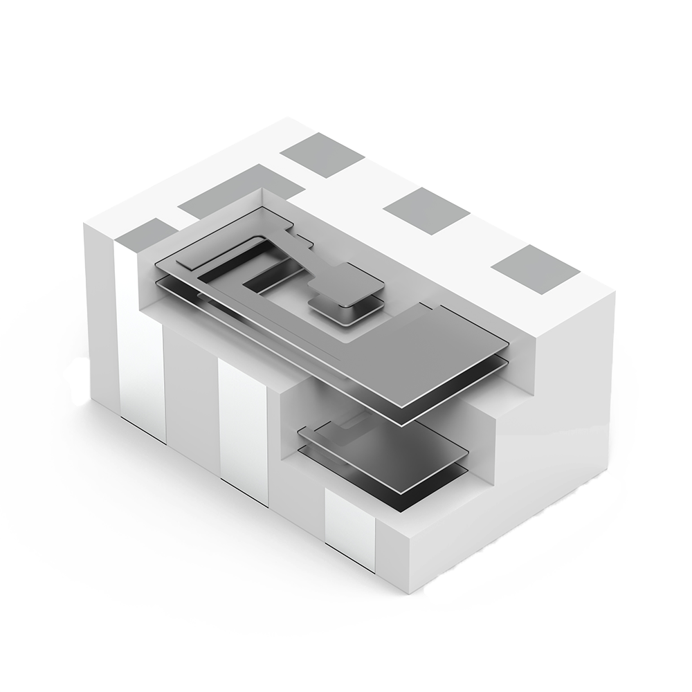
LTCC internal structure
Multilayer Chip Balun
BALanced-UNbalanced
Multilayer Chip Balun
BALanced-UNbalanced
A balun (balance - unbalance) is a device that converts between balanced (symmetric) and unbalanced (unsymmetric) signals and may or may not transform impedances, depending on the application. It is a three-port power splitter, designed for a certain specific frequency, bandwidth and impedance. With modern trends in technology, RF transceivers are increasingly utilizing more and more differential topologies due to the inherent benefit of noise reduction and a balun is always needed to adapt the signal between single ended(unbalanced) and a differential(balanced) transmission line. For example, between IC and antenna.
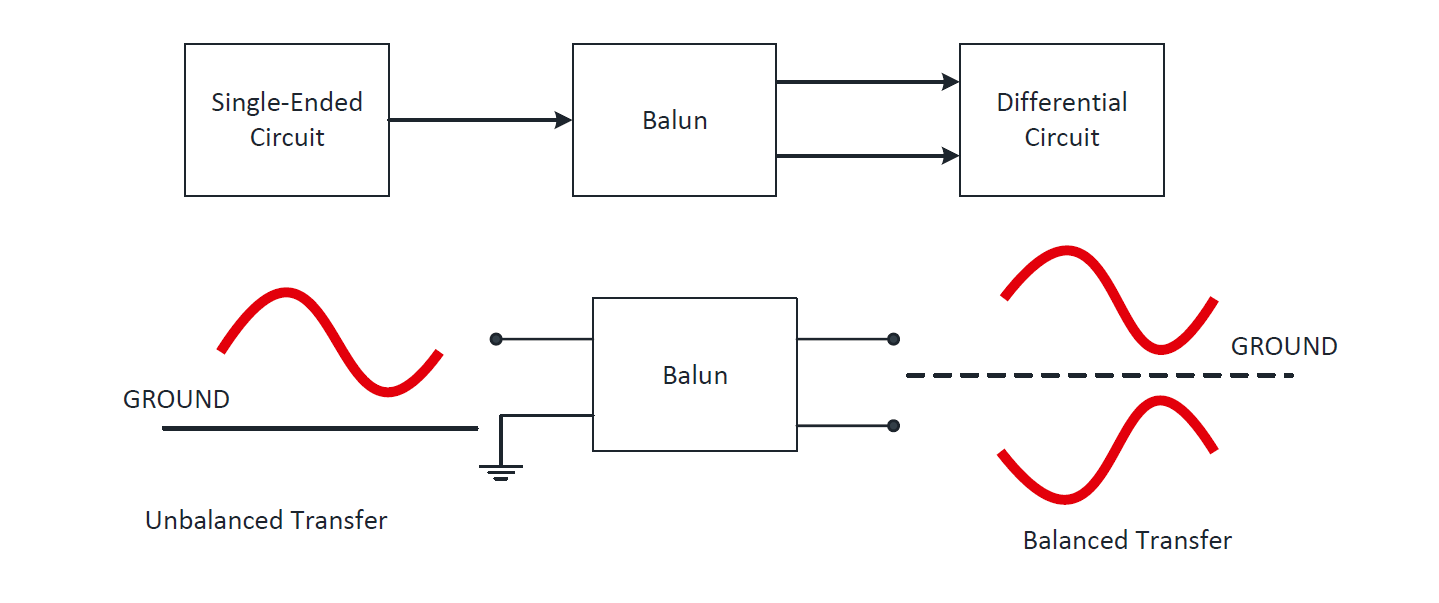
Balun parameters
Insertion Loss
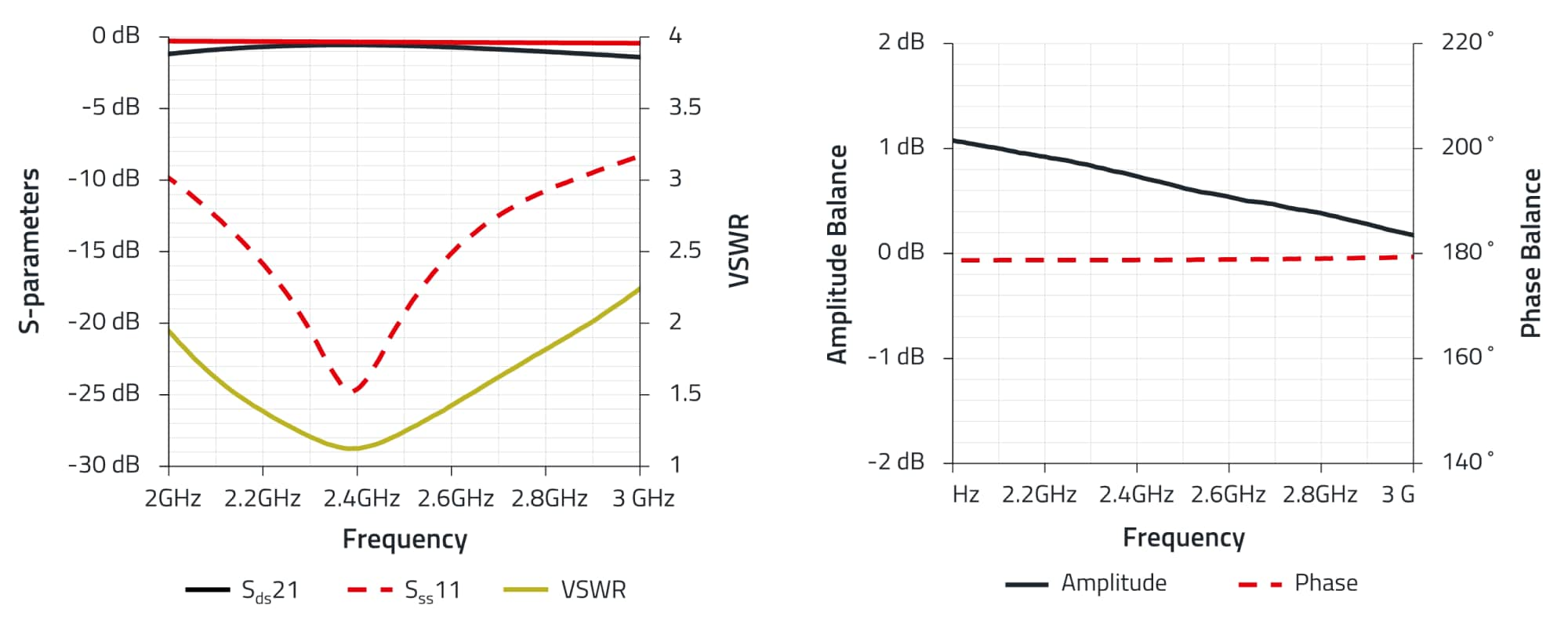
Insertion Loss describes the amount of loss in the system and is expressed in dB (decibels). Here it means the amount of loss in signal, due to travelling into and out of the balun . It can be calculated with the help of S-parameters, given the measurement ports are using the same reference impedance. Due to high quality and standards, typical insertion loss values are less than 1.5 dB.
Amplitude- and phase balance
Amplitude- and phase balance describe how accurately the signal is matched between the differential lines. Phase balance gives the difference in phase between the balanced lines, whereas amplitude balance is the measure of how well matched the output power is, between the balanced ports. Typical tolerance values for phase balance are ± 10° and for amplitude balance is ±1 dB.
Unbalanced- and balanced Impedance
Is the impedance of single ended and differential lines, depending upon the requirements. Baluns are bidirectional passive devices, used to convert between balanced and unbalanced signals and impedances. One of the most important functions of a balun is to transform the impedance between single-ended and differential lines.
Typical Application
Types and applications
Würth Elektronik RF-balun portfolio includes multilayer SMD baluns with balanced impedances of 50, 100 and 200 Ω in the sizes 0603 and 0805 with the working frequency ranges from 673 MHz to 5900MHz. Most common applications for these baluns include WiFi, Bluetooth, wireless communication systems and IoT enabled devices. Due to LTCC based technology, high performance is achieved with minimal insertion loss in the frequency band of interest.


