Details
| Topologie | Abwärtswandler |
| Eingangsspannung | 2.9-18 V |
| Schaltfrequenz | 900-1100 kHz |
| Ausgang 1 | 1.2 V / 5 A |
| Ausgang 2 | 5 V / 5 A |
| Ausgang 3 | 3.3 V / 5 A |
| Ausgang 4 | 1.8 V / 5 A |
Beschreibung
Evaluation kit DC2851A is a quad-channel synchronous step-down regulator featuring the LT7200S. The LT7200S is ideal for high step-down ratio applications that operate at high frequency while demanding fast transient response thanks to its constant frequency, current-mode architecture, and phase-lockable controlled on-time. The DC2851A operates from an input voltage range of 2.9V to 18V, with each regulator capable of delivering ±5A of output current. The evaluation kit is designed for 1.2V, 1.8V, 3.3V, and 5V outputs with switching frequency set at 1MHz. The DC2851A provides LT7200S-based different multichannel combinations for flexible output current rating.The LT7200S features independent soft-start, output tracking and power good for each output to simplify the complex design of quad-output converters. The output tracking and soft-start pins allows to control the rise time and ramp rate of the output voltage. Each output can be independently disabled into the low quiescent current shutdown mode with its own TRACK or RUN pin.A user-selectable MODE/SYNC pin on the evaluation kit allows the part to operate in either discontinuous mode for higher efficiency at light load currents, or forced continuous mode for lower output ripple at the expense of light load efficiency. The MODE/SYNC pin can also be used to synchronize the switching frequency to an external clock. The switching frequency for all regulators can be programmed either through the oscillator resistor or external clock over a 400kHz to 3MHz range. At all frequencies, a 180° phase shift is maintained between channel 1 and channel 2, channel 3 and channel 4 when PHMODE pin is low, reducing the input peak current and voltage ripple.The DC2851A has an EMI filter installed on the bottom layer. The conducted and radiated EMI performance of the board is shown in Figure 4. The red line in Figure 4 is the CISPR25 Class 5 peak limit. The figure shows that the circuit passes the test with a wide margin. To achieve EMI/ EMC performance as shown in Figure 4, the input EMI filter is required, and the input voltage should be applied at VEMI turret.The LT7200S data sheet gives a complete description of the part operation and application information. Read the data sheet in conjunction with this quick start guide for DC2851A. The LT7200S is assembled in a 5mm × 6mm LQFN package with exposed pads for low thermal resistance. Proper board layout is essential for both low EMI operation and best thermal performance.
Eigenschaften
- Silent Switcher 2 Architecture:
- Ultralow EMI
- Eliminated PCB Layout Sensitivity
- Internal Bypass Caps Reduce Radiated EMI
- Wide SVIN Range: 2.9V to 18V; PVIN: 1.5V to 18V
- Wide VOUT Range: 0.5V to 0.9VIN
- Output Current: ±5A/ Channel; up to ±20A
- Accurate Reference: 0.5V ± 0.8% Over Temp
- High Efficiency: Up to 96%
- 12ns Min on-time: True 12V to 1V at 2MHz
- Programmable Multi-phase, Synchronizable Frequency: 400kHz to 3MHz
- Current Mode: Excellent Line and Load Transient Response
- User Selectable Discontinuous Mode® (DCM) or Forced Continuous Mode (FCM) Operation
- Flexible Individual Internal Compensation for Ease of Use; External for Fast Transient
- Accurate Individual 1.2V EN/ Run Pin Threshold
- Individual Output Tracking and Soft-Start
- Individual Power Good Status Output
- Low Profile 5mm x 6mm 48-Lead LQFN Package
Typische Anwendungen
- Distributed Power Systems, Server Power, Point of Load Supply for ASIC, FPGA, Etc.
Weiterführende Informationen
Artikeldaten
| Artikel Nr. | Datenblatt | Simulation | Downloads | Status | Produktserie | L (µH) | IRP,40K (A) | ISAT,10% (A) | ISAT,30% (A) | RDC max. (mΩ) | fres (MHz) | Montageart | Z @ 100 MHz (Ω) | Zmax (Ω) | Testbedingung Zmax | IR (mA) | Z @ 1 GHz (Ω) | H (mm) | Typ | Pins (pcs) | Raster (mm) | Reihen | Gender | Verpackung | Muster | |
|---|---|---|---|---|---|---|---|---|---|---|---|---|---|---|---|---|---|---|---|---|---|---|---|---|---|---|
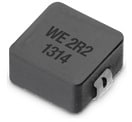 | 744373360033 | SPEC | 9 Dateien | Aktiv i| Produktion ist aktiv. Erwartete Lebenszeit: >10 Jahre. | WE-LHMI SMT Speicherdrossel | 0.33 | 15.1 | 15 | 29.3 | 5 | 120 | SMT | – | – | – | – | – | 2.8 | – | 2 | – | – | – | – | ||
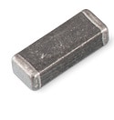 | 74279226101 | SPEC | 10 Dateien | Aktiv i| Produktion ist aktiv. Erwartete Lebenszeit: >10 Jahre. | WE-MPSB EMI Multilayer Power Suppression Bead | – | – | – | – | 6 | – | SMT | 100 | 160 | 1100 MHz | 8000 | 150 | 2.3 | Hochstrom | – | – | – | – | – | ||
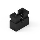 | 60800213421 | SPEC | – | 3 Dateien | Aktiv i| Produktion ist aktiv. Erwartete Lebenszeit: >10 Jahre. | WR-PHD Jumper | – | – | – | – | – | – | – | – | – | – | 3000 | – | – | – | 2 | 2 | – | Jumper | Beutel | |
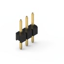 | 62000311121 | SPEC | – | 7 Dateien | Aktiv i| Produktion ist aktiv. Erwartete Lebenszeit: >10 Jahre. | WR-PHD Pin Header | – | – | – | – | – | – | THT | – | – | – | 2000 | – | – | Gerade | 3 | 2 | Single | Stiftleiste | Beutel | |
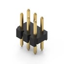 | 62000621121 | SPEC | – | 7 Dateien | Aktiv i| Produktion ist aktiv. Erwartete Lebenszeit: >10 Jahre. | WR-PHD Pin Header | – | – | – | – | – | – | THT | – | – | – | 2000 | – | – | Gerade | 6 | 2 | Dual | Stiftleiste | Beutel |
| Artikel Nr. | Datenblatt | Simulation | |
|---|---|---|---|
 | 744373360033 | SPEC | |
 | 74279226101 | SPEC | |
 | 60800213421 | SPEC | – |
 | 62000311121 | SPEC | – |
 | 62000621121 | SPEC | – |
| Muster |
|---|
| Artikel Nr. | Datenblatt | Simulation | Downloads | Status | Produktserie | L (µH) | IRP,40K (A) | ISAT,10% (A) | ISAT,30% (A) | RDC max. (mΩ) | fres (MHz) | Montageart | Z @ 100 MHz (Ω) | Zmax (Ω) | Testbedingung Zmax | IR (mA) | Z @ 1 GHz (Ω) | H (mm) | Typ | Pins (pcs) | Raster (mm) | Reihen | Gender | Verpackung | Muster |
|---|


