IC-Hersteller (104)
- Alle Hersteller
 Analog Devices
 Infineon Technologies
 Microchip
 Onsemi
 Renesas
 ROHM
ROHM STMicroelectronics
 Texas Instruments
- 3peak incorporated (28)
- Ablic (23)
- Acco Semiconductor (1)
- Advanced Power (4)
- Allegro Microsystems (97)
- Alpha & Omega Semiconductor (37)
- AnalogySemi (3)
- AnDAPT Inc (204)
- Anpec (13)
- AXElite (2)
- Backward (6)
- Bright Power Semiconductor (1)
- Broadcom (45)
- Cambridge GaN Devices (18)
- Chipanalog Micro (10)
- Cologne Chips (1)
- Convenient Power (1)
- Dialog Semiconductor (12)
- Diodes Incorporated (255)
- Divimath (8)
- Elmos AG (1)
- EPC (135)
- e-Peas Semiconductors (1)
- Eta Solutions Co. Ltd. (9)
- GaN Systems (8)
- GaNPower (3)
- Giantec (1)
- Gstek Wuxi (1)
- Helix Semiconductor (7)
- IKON (1)
- Indie Semiconductor (8)
- Innovision Semiconductor Inc (2)
- Intel (68)
- Inventchip Technology (3)
- ISSI (51)
- JoulWatt (20)
- KDPOF (3)
- Kinetic Technology (8)
- Lattice semiconductor Corporation (30)
- Littelfuse (1)
- Lumissil Microsystems (8)
- M3 Technology (M3Tek) (7)
- Macnica (22)
- Marvell Semiconductor (1)
- MaxLinear (181)
- Menlo Micro (1)
- MikroE (21)
- MindCet (2)
- Monolithic Power Systems (979)
- Navitas Semiconductor Inc (6)
- NewEdge Technologies, Inc. (1)
- Nexperia (263)
- Nisshinbo Micro Device Inc. (10)
- Nordic Semiconductor (1)
- Novosense Micro (1)
- NXP (327)
- O2 Micro International Ltd (10)
- On Bright (7)
- Panasonic (2)
- PN Junction Semiconductor (2)
- Power Integrations (120)
- Powermat (1)
- Pulsiv (19)
- Qorvo (95)
- Realsil SuRealsil(tek) Microelectronics (1)
- Richtek (297)
- Sanken Electric Co., Ltd. (16)
- Sckipio (6)
- Semtech (87)
- SG-Micro (49)
- SiFive (2)
- Silanna Semiconductor (9)
- Silergy Corporation (33)
- Silicon Laboratory Inc. (103)
- Silicontent Technology (59)
- Silvertel (61)
- Skycore Semiconductors (1)
- Skyworks (33)
- Southchip (8)
- Summit Wireless (1)
- Tagore Tech (7)
- Taiwan Semiconductor (1)
- TDK Corporation (1)
- Tempo Semiconductor (1)
- Torex (37)
- Toshiba (25)
- Transphorm (21)
- TransSIP (2)
- Union (21)
- uPI Semiconductor (2)
- Valens Semiconductor (30)
- Wise Integration (1)
- Wolfspeed (23)
- Xilinx (22)
- XL Semiconductor (3)
- XYSemi (62)
Details
| Topologie | Abwärts- und Aufwärtswandler |
| Eingangsspannung | 4-60 V |
| Schaltfrequenz | 600-2000 kHz |
| Ausgang 1 | 15 V / 1.5 A |
| IC-Revision | 1 |
Beschreibung
Demonstration circuit DC2575A is a 60V 2MHz synchronousbuck-boost LED driver featuring the LT8391A. Itaccepts an input voltage from 4V to 60V and drives asingle string of LEDs up to 16V at 1.5A. DC2575A runs at2MHz switching frequency without spread spectrum, butspread spectrum frequency modulation (SSFM) can beenabled with a simple jumper. SSFM spreads the switchingfrequency from fSW to fSW+25% for reduced EMI.DC2575A uses AEC-Q automotive-approved componentssuch as power MOSFETs, diodes, input and output capacitorsand inductors.The LT8391A has a wide input voltage range down to4V and up to 60V. It has adjustable switching frequencybetween 600kHz and 2MHz. There is a simple jumperoption for external frequency synchronization, spreadspectrum frequency modulation, or neither.The LT8391A can be PWM dimmed with an external PWMsignal and an internally-generated PWM signal. DC2575Ahas a jumper that can be set to switch between internallygeneratedPWM signal, externally-generated PWM signal,and no PWM signal (100% on). It can be analog dimmedwith a control voltage on either of its two control pins.LT8391A features both open LED and short LED (LED+ toGND) protection as well as a fault output flag.When run with both PWM dimming and spread spectrum,the spread spectrum aligns itself with the PWM signal forflicker-free operation.Small ceramic input and output capacitors are used tosave space and cost. The board is designed with capacitorson both sides of the synchronous switches for areduction in radiated EMI. The open LED overvoltageprotection uses the IC’s constant voltage regulation loopto regulate the output to approximately 18V if the LEDstring is opened. There is a protection diode from LED+to GND to prevent negative ringing during a short-circuitwith long wires.Undervoltage lockout can be adjusted on the circuit witha few simple resistor choices.EMI filters and gate resistors on the demo circuit reducethis high power converter’s EMI below CISPR 25 Class 5limits. This is intended for automotive applications whereCISPR 25 EMI standards are observed. In non-automotiveapplications, the EMI may not be as important and theinput and output filters, as well as the gate resistors canbe removed for higher efficiency. Please note the optionalEMI components in the parts list. SSFM is also used toreduce EMI and is not necessary in applications whereEMI is not important.The LT8391A data sheet gives a complete description ofthe part, operation and applications information. The datasheet must be read in conjunction with this Demo Manualfor demonstration circuit DC2575A. The LT8391AIFE isassembled in a 28-lead plastic TSSOP (FE) package witha thermally-enhanced ground pad. Proper board layoutis essential for maximum thermal performance. See thedata sheet section "Layout Considerations".
Eigenschaften
PJ17US007342
Weiterführende Informationen
Artikeldaten
| Artikel Nr. | Datenblatt | Downloads | Status | Produktserie | L (mm) | f (mm) | Pins (pcs) | Raster (mm) | Reihen | Gender | Typ | IR (A) | Verpackung | Muster | |
|---|---|---|---|---|---|---|---|---|---|---|---|---|---|---|---|
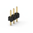 | 62000311121 | SPEC | 7 Dateien | Aktiv i| Produktion ist aktiv. Erwartete Lebenszeit: >10 Jahre. | WR-PHD Pin Header | 6 | – | 3 | 2 | Single | Stiftleiste | Gerade | 2 | Beutel | |
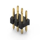 | 62000621121 | SPEC | 7 Dateien | Aktiv i| Produktion ist aktiv. Erwartete Lebenszeit: >10 Jahre. | WR-PHD Pin Header | 6 | – | 6 | 2 | Dual | Stiftleiste | Gerade | 2 | Beutel | |
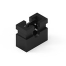
 | 702933000 | SPEC | 3 Dateien | Aktiv i| Produktion ist aktiv. Erwartete Lebenszeit: >10 Jahre. | WA-SNSR Self-Retaining Spacer | 9.5 | 4.8 | – | – | – | – | – | – | – | |
 | 60800213421 | SPEC | 3 Dateien | Aktiv i| Produktion ist aktiv. Erwartete Lebenszeit: >10 Jahre. | WR-PHD Jumper | – | – | 2 | 2 | – | Jumper | – | 3 | Beutel |
| Artikel Nr. | Datenblatt | |
|---|---|---|
| 62000311121 | SPEC |
| 62000621121 | SPEC |
| 702933000 | SPEC |
| 60800213421 | SPEC |
| Muster |
|---|
| Artikel Nr. | Datenblatt | Downloads | Status | Produktserie | L (mm) | f (mm) | Pins (pcs) | Raster (mm) | Reihen | Gender | Typ | IR (A) | Verpackung | Muster |
|---|
