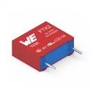
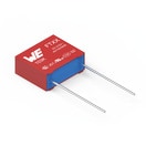
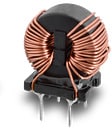
Microchip MCP14A0452 | Demoboard Digital power kit (PFC) 50W
4.5A MOSFET Driver With Low Threshold Input and Enable
Details
| Topologie | Leistungsfaktor-Korrektur |
| Eingangsspannung | 12-26 V |
| Schaltfrequenz | 10-1000 kHz |
| Ausgang 1 | 42 V / 1.3 A |
| IC-Revision | 5 |
Beschreibung
The MCP14A0451/2 devices are high-speed MOSFETdrivers that are capable of providing up to 4.5A of peakcurrent while operating from a single 4.5V to 18Vsupply. There are two output configurations available;inverting (MCP14A0451) and non-inverting(MCP14A0452). These devices feature low shootthroughcurrent, fast rise and fall times, and shortpropagation delays which make them ideal for highswitching frequency applications.The MCP14A0451/2 family of devices offer enhancedcontrol with Enable functionality. The active-highEnable pin can be driven low to drive the output of theMCP14A0451/2 low, regardless of the status of theInput pin. An integrated pull-up resistor allows the userto leave the Enable pin floating for standard operation.These devices are highly latch-up resistant under anycondition within their power and voltage ratings. Theycan accept up to 500 mA of reverse current beingforced back into their outputs without damage or logicupset. All terminals are fully protected againstelectrostatic discharge (ESD) up to 2 kV (HBM) and200V (MM).
Eigenschaften
- High Peak Output Current: 4.5A (typical)
- Wide Input Supply Voltage Operating Range: 4.5V to 18V
- Low Shoot-Through/Cross-Conduction Current in Output Stage
- High Capacitive Load Drive Capability: 2200 pF in 9.5 ns (typical) -
- Short Delay Times: 16 ns (tD1), 19.5 ns (tD2) (typical)
- Low Supply Current: 355 μA (typical)
- Low-Voltage Threshold Input and Enable with Hysteresis
- Latch-Up Protected: Withstands 500 mA Reverse Current
- Space-Saving Packages:
- 8-Lead MSOP
- 8-Lead SOIC
- 8-Lead 2 x 2 DFN
Typische Anwendungen
- Switch Mode Power Supplies / Pulse Transformer Drive / Line Drivers
- Motor and Solenoid Drive
Weiterführende Informationen
Artikeldaten
| Artikel Nr. | Datenblatt | Simulation | Downloads | Status | Produktserie | Anwendung | C | Sicherheitsklasse | dV/dt (V/µs) | DF @ 1 kHz (%) | RISO | Raster (mm) | Verpackung | ISAT (A) | Endurance (h) | IRIPPLE (mA) | ILeak (µA) | DF (%) | Ø D (mm) | IR (A) | L (mH) | RDC max. (mΩ) | VR (V (AC)) | VT (V (AC)) | Material | L (mm) | W (mm) | H (mm) | Montageart | Muster | |
|---|---|---|---|---|---|---|---|---|---|---|---|---|---|---|---|---|---|---|---|---|---|---|---|---|---|---|---|---|---|---|---|
 | 890324025034CS | SPEC | 9 Dateien | Aktiv i| Produktion ist aktiv. Erwartete Lebenszeit: >10 Jahre. | WCAP-FTX2 Folienkondensatoren | Across the mains | 330 nF | X2 | 260 | 0.1 | 30 GΩ | 15 | Karton | – | – | – | – | – | – | – | – | – | 275 | – | – | 18 | 8.5 | 14.5 | Boxed THT | ||
 | 890334024005CS | SPEC | 9 Dateien | Aktiv i| Produktion ist aktiv. Erwartete Lebenszeit: >10 Jahre. | WCAP-FTXX Folienkondensatoren | Across the mains | 470 nF | X2 | 280 | 0.1 | 21.28 GΩ | 12.5 | Karton | – | – | – | – | – | – | – | – | – | 310 | – | – | 15 | 10 | 16 | Boxed THT | ||
 | 890334025045 | SPEC | 9 Dateien | Aktiv i| Produktion ist aktiv. Erwartete Lebenszeit: >10 Jahre. | WCAP-FTXX Folienkondensatoren | Across the mains | 680 nF | X2 | 230 | 0.1 | 14.71 GΩ | 15 | Lose | – | – | – | – | – | – | – | – | – | 310 | – | – | 18 | 10 | 16 | Boxed THT | ||
 | 7448031002 | SPEC | 11 Dateien | Aktiv i| Produktion ist aktiv. Erwartete Lebenszeit: >10 Jahre. | WE-CMBNC Stromkompensierte Netzdrossel Nanokristallin | – | – | – | – | – | – | – | – | – | – | – | – | – | – | 10 | 2 | 6.3 | 300 | 2100 | Nanokristallin | 24 | 17 | 25 | THT | ||
 | 744750230047 | SPEC | 8 Dateien | Aktiv i| Produktion ist aktiv. Erwartete Lebenszeit: >10 Jahre. | WE-FAMI THT Speicherdrossel | – | – | – | – | – | – | – | – | 9.6 | – | – | – | – | – | 6.5 | 0.0047 | 12.5 | – | – | – | 8.8 | 8.8 | 11 | THT | ||
 | 860010572005 | SPEC | 8 Dateien | Aktiv i| Produktion ist aktiv. Erwartete Lebenszeit: >10 Jahre. | WCAP-ATG8 Aluminium-Elektrolytkondensatoren | – | 47 µF | – | – | – | – | 2 | Ammopack | – | 2000 | 143 | 16.45 | 12 | 5 | – | – | – | 35 | – | – | 11 | – | – | – | ||
 | 860010680026 | SPEC | 8 Dateien | Aktiv i| Produktion ist aktiv. Erwartete Lebenszeit: >10 Jahre. | WCAP-ATG8 Aluminium-Elektrolytkondensatoren | – | 1500 µF | – | – | – | – | 7.5 | Ammopack | – | 2000 | 1848 | 750 | 10 | 16 | – | – | – | 50 | – | – | 31.5 | – | – | – | ||
 | 860080774008 | SPEC | 8 Dateien | Aktiv i| Produktion ist aktiv. Erwartete Lebenszeit: >10 Jahre. | WCAP-ATLI Aluminium-Elektrolytkondensatoren | – | 47 µF | – | – | – | – | 3.5 | Ammopack | – | 3000 | 400 | 29.61 | 8 | 8 | – | – | – | 63 | – | – | 11.5 | – | – | – | ||
| 750316197 | SPEC | – | – | Aktiv i| Produktion ist aktiv. Erwartete Lebenszeit: >10 Jahre. | PFC Inductor | – | – | – | – | – | – | – | – | – | – | – | – | – | – | – | – | – | – | – | – | – | – | – | – |
| Artikel Nr. | Datenblatt | Simulation | |
|---|---|---|---|
 | 890324025034CS | SPEC | |
 | 890334024005CS | SPEC | |
 | 890334025045 | SPEC | |
 | 7448031002 | SPEC | |
 | 744750230047 | SPEC | |
 | 860010572005 | SPEC | |
 | 860010680026 | SPEC | |
 | 860080774008 | SPEC | |
| 750316197 | SPEC | – |
| Muster |
|---|
| Artikel Nr. | Datenblatt | Simulation | Downloads | Status | Produktserie | Anwendung | C | Sicherheitsklasse | dV/dt (V/µs) | DF @ 1 kHz (%) | RISO | Raster (mm) | Verpackung | ISAT (A) | Endurance (h) | IRIPPLE (mA) | ILeak (µA) | DF (%) | Ø D (mm) | IR (A) | L (mH) | RDC max. (mΩ) | VR (V (AC)) | VT (V (AC)) | Material | L (mm) | W (mm) | H (mm) | Montageart | Muster |
|---|


