Details
| Topologie | Sonstige Topologie |
| Eingangsspannung | 3.3-12 V |
| IC-Revision | 01-01 |
Beschreibung
This hardware manual describes the design of the VSC5640EV reference board, demonstrating the SparX-5-200/VSC7558 Ethernet Switch device. The VSC5640EV reference board is based on PCB134 Reference Design schematic. Regarding basic board design, the SparX-5-200/VSC7558 and its derivatives, like: SparX-5-64/ 5 VSC7546, SparX-5 90/VSC7549, SparX-5-128/VSC7552 and SparX-5-160/VSC7556 are all very similar devices. They use the same BGA package, pin layout, number of SerDes macros and types,and incorporate the VCore-IV CPU system and associated interfaces. The main difference is the maximum bandwidth supported. The VSC5640EV reference board supports all these derivatives.
Eigenschaften
- 1x VSC7558 Switch (with Enterprise Ethernet features)
- 12x SFP+ front 10G module slots connected to VSC7558 through SFI
- 8x SFP28 front 25G module slots connected to VSC7558 through SFI high speed
- Optional, one additional 10/100/1000BASE-T (RJ45) Ethernet port using an on-board VSC8211 PHY, which can be connected to VSC7558 NPI port through SGMII by adding a loopback add-on PCB.
- On board Sync-E DPLL Redwood/ZL30772LFG7Q05S (replaceable with the cheaper non-PTP ZL30256, if SyncE and PTP operation is not required) to generate the 3 required clocks. Additional support for a range of Microchip Sync-E module designs through a Sync-E feature connector – note, that all clocks still go through the on-board DPLL.
- Four SMAs connectors and two ITU-T G.8275 compliant RS422 interfaces (1 PPS + ToD input and output) for Sync-E and PTP applications.
- Serial UART port (USB) for local management and software debugging by using a firmware driven Command Line Interface (CLI).
- Reset button at rear, and user input button on front.
- System status LED (bi-color green/red) and port status LED (bi-color green/yellow) per network port for link and activity indication.
- Standard 240/110VAC 200W PSU.
Typische Anwendungen
- Ethernet switches
Weiterführende Informationen
Artikeldaten
| Artikel Nr. | Datenblatt | Downloads | Status | Produktserie | Ti | Ø OD (mm) | Ø ID (mm) | Verpackung | VPE | Pins (pcs) | Raster (mm) | Version | Gender | Typ | Montageart | IR (A) | Arbeitsspannung (V (AC)) | Betriebstemperatur | Kontaktwiderstand (mΩ) | Tol. R | Ausführung | Haltbarkeit | Anwendung | Interface typ | IR 1 (mA) | Poles | L (mm) | Dampfphasenprozess | Muster | |
|---|---|---|---|---|---|---|---|---|---|---|---|---|---|---|---|---|---|---|---|---|---|---|---|---|---|---|---|---|---|---|
 | 9774030151R | SPEC | 6 Dateien | Aktiv i| Produktion ist aktiv. Erwartete Lebenszeit: >10 Jahre. | WA-SMSI SMT Stahl Spacer mit Innengewinde M2.5 | M2.5 | 5.1 | 3.5 | Tape and Reel | 700 | – | – | – | – | – | – | – | – | -55 °C up to +150 °C | – | – | – | – | – | – | – | – | 3 | – | |
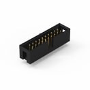
 | 61202021621 | SPEC | 8 Dateien | Aktiv i| Produktion ist aktiv. Erwartete Lebenszeit: >10 Jahre. | WR-BHD 2.54 mm Male | – | – | – | Tray | – | 20 | 2.54 | Low Profile | Männlich | Gerade | THT | 3 | 250 | -40 °C up to +105 °C | 20 | max. | – | 30 Steckzyklen | – | – | – | – | 33.06 | – | |
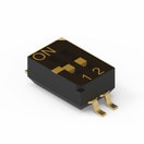
 | 416131160802 | SPEC | 6 Dateien | Aktiv i| Produktion ist aktiv. Erwartete Lebenszeit: >10 Jahre. | WS-DISV Small Compact SMT Flat Actuator with Top Tape 1.27 mm | – | – | – | Tape and Reel | 2000 | 2 | 1.27 | – | – | – | – | – | – | -40 °C up to +85 °C | – | – | – | – | – | – | 25 | 2 | 3.71 | Ja | |
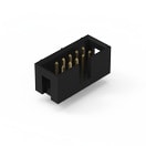
 | 61201021621 | SPEC | 7 Dateien | Aktiv i| Produktion ist aktiv. Erwartete Lebenszeit: >10 Jahre. | WR-BHD 2.54 mm Male | – | – | – | Tray | – | 10 | 2.54 | Low Profile | Männlich | Gerade | THT | 3 | 250 | -40 °C up to +105 °C | 20 | max. | – | 30 Mating cycles | – | – | – | – | 20.36 | – | |
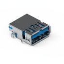
 | 692122030100 | SPEC | 6 Dateien | Aktiv i| Produktion ist aktiv. Erwartete Lebenszeit: >10 Jahre. | WR-USB Standard Connectors | – | – | – | Tape and Reel | – | 9 | – | – | Buchse | Horizontal | SMT | 1.8 | 30 | -20 °C up to +85 °C | 30 | max. | Mit Pegs | 5 000 Steckzyklen | USB 3.0 | Type A | 250 | – | – | – | |
 | 693071010811 | SPEC | 6 Dateien | Aktiv i| Produktion ist aktiv. Erwartete Lebenszeit: >10 Jahre. | WR-CRD SD Card Connectors | – | – | – | Tape and Reel & Mylar | – | 8 | – | – | Buchse | Push & Push | SMT | 0.5 | 100 | -25 °C up to +85 °C | 100 | max. | Mit Kartenerkennung | 10 000 Mating cycles | Micro SD | – | – | – | – | – |
| Artikel Nr. | Datenblatt | |
|---|---|---|
 | 9774030151R | SPEC |
 | 61202021621 | SPEC |
 | 416131160802 | SPEC |
 | 61201021621 | SPEC |
 | 692122030100 | SPEC |
 | 693071010811 | SPEC |
| Muster |
|---|
| Artikel Nr. | Datenblatt | Downloads | Status | Produktserie | Ti | Ø OD (mm) | Ø ID (mm) | Verpackung | VPE | Pins (pcs) | Raster (mm) | Version | Gender | Typ | Montageart | IR (A) | Arbeitsspannung (V (AC)) | Betriebstemperatur | Kontaktwiderstand (mΩ) | Tol. R | Ausführung | Haltbarkeit | Anwendung | Interface typ | IR 1 (mA) | Poles | L (mm) | Dampfphasenprozess | Muster |
|---|


