STMicroelectronics STWBC-MC | Demoboard STEVAL-ISB047V1
Qi 3-coil 15W wireless charger TX evaluation kit based on STWBC-MC
Details
| Topologie | Drahtlose Energieübertragung |
| Eingangsspannung | 5-20 V |
| IC-Revision | 1 |
Beschreibung
The STEVAL-ISB047V1 wireless battery charger TX evaluation kit consists of the STEVAL-ISB047V1T evaluation board and STEVAL-WBCDNGV1 USB-UART dongle. The kit id designed for charging devices such as smartphones or tablets where high power levels are required.The evaluation board supports wireless battery charging of Qi-compliant devices up to 15 W. It also supports proprietary fast charging modes up to 10 W.The STEVAL-ISB047V1 transmitter is based on the STWBC-MC and features a costeffective half bridge topology, offering external interface via UART.The STEVAL-ISB047V1 evaluation kit is a full solution, complete with boards, firmware, a GUI for debugging, schematics, layout files and bill of materials.Tools for STEVAL-ISB047V1 are available on www.st.com, and allow users to access runtime information such as power delivered, regulation error and protocol status. Parameters can also be adjusted with these tools.
Eigenschaften
- STWBC-MC digital controller
- MP-A15 3-coil array
- 15 W potential power
- Flexible input voltage: 5 to 20 V from USB-C or DC jack
- 5 W mode when connected to 5 V USB input or DC jack
- Fixed frequency operation
- WPC Qi1.2.4 standard certified
- Robust demodulation algorithm, with triple path (V, I, f)
- Foreign object detection (FOD)
- Active presence detection
- UART protocol to control and monitor the system
- Complete reference design (evaluation board, schematics, PCB layout, firmware and tools)
- 2-layer PCB
- Low standby power consumption
- Flash memory based
- CE certified
- RoHS compliant
- WEEE compliant
Typische Anwendungen
- Cell phones and smartphones / Tablets and phablets / Charging accessories
Weiterführende Informationen
Artikeldaten
| Artikel Nr. | Datenblatt | Simulation | Downloads | Status | Produktserie | λDom typ. (nm) | Farbe | λPeak typ. (nm) | IV typ. (mcd) | VF typ. (V) | Chiptechnologie | 2θ50% typ. (°) | C | Tol. C | VR (V (DC)) | Betriebstemperatur | DF (%) | RISO | Keramiktyp | L (mm) | W (mm) | H (mm) | Fl (mm) | Verpackung | L (µH) | IR (mA) | ISAT (A) | RDC (mΩ) | Anwendung | Interface typ | Ausführung | Gender | Pins (pcs) | Montageart | IR 1 (mA) | Arbeitsspannung (V (AC)) | Raster (mm) | Reihen | G (mm) | Z @ 100 MHz (Ω) | Zmax (Ω) | Testbedingung Zmax | IR 2 (mA) | RDC max. (Ω) | Typ | L1 (µH) | L2 (µH) | IR 1 (mA) | ISAT 1 (A) | RDC1 typ (Ω) | RDC2 typ (Ω) | RDC1 max (Ω) | RDC2 max (Ω) | fres (MHz) | Compliance | Bauform | L1 (µH) | L2 (µH) | L3 (µH) | IR DC1 (A) | IR DC2 (A) | IR DC3 (A) | RDC1 max. (Ω) | RDC2 max. (mΩ) | RDC3 max. (mΩ) | fres 1 (MHz) | fres 2 (MHz) | fres 3 (MHz) | P (W) | Muster | |
|---|---|---|---|---|---|---|---|---|---|---|---|---|---|---|---|---|---|---|---|---|---|---|---|---|---|---|---|---|---|---|---|---|---|---|---|---|---|---|---|---|---|---|---|---|---|---|---|---|---|---|---|---|---|---|---|---|---|---|---|---|---|---|---|---|---|---|---|---|---|---|---|
 | 155124VS73200 | SPEC | 6 Dateien | Aktiv i| Produktion ist aktiv. Erwartete Lebenszeit: >10 Jahre. | WL-SMSW SMT Mono-color Side View Waterclear | 573 | Hellgrün | 575 | 50 | 2 | AlInGaP | 120 | – | – | – | -40 °C up to +85 °C | – | – | – | 3.2 | 1.5 | 1 | – | Tape and Reel | – | – | – | – | – | – | – | – | – | SMT | – | – | – | – | – | – | – | – | – | – | – | – | – | – | – | – | – | – | – | – | – | 1204 | – | – | – | – | – | – | – | – | – | – | – | – | – | ||
 | 155124RS73200 | SPEC | 6 Dateien | Aktiv i| Produktion ist aktiv. Erwartete Lebenszeit: >10 Jahre. | WL-SMSW SMT Mono-color Side View Waterclear | 624 | Rot | 632 | 130 | 2 | AlInGaP | 120 | – | – | – | -40 °C up to +85 °C | – | – | – | 3.2 | 1.5 | 1 | – | Tape and Reel | – | – | – | – | – | – | – | – | – | SMT | – | – | – | – | – | – | – | – | – | – | – | – | – | – | – | – | – | – | – | – | – | 1204 | – | – | – | – | – | – | – | – | – | – | – | – | – | ||
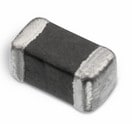 | 74279262 | SPEC | 9 Dateien | Aktiv i| Produktion ist aktiv. Erwartete Lebenszeit: >10 Jahre. | WE-CBF SMT-Ferrit | – | – | – | – | – | – | – | – | – | – | -55 °C up to +125 °C | – | – | – | 1.6 | 0.8 | 0.8 | 0.3 | – | – | 500 | – | – | – | – | – | – | – | SMT | 500 | – | – | – | – | 120 | 200 | 510 MHz | 1350 | 0.3 | Breitband | – | – | 500 | – | – | – | – | – | – | – | 0603 | – | – | – | – | – | – | 0.3 | – | – | – | – | – | – | ||
 | 74404054022 | SPEC | 9 Dateien | Aktiv i| Produktion ist aktiv. Erwartete Lebenszeit: >10 Jahre. | WE-LQS SMT-Speicherdrossel | – | – | – | – | – | – | – | – | – | – | -40 °C up to +125 °C | – | – | – | 5 | 5 | 4 | – | – | 2.2 | 3800 | 5.3 | 19 | – | – | – | – | – | SMT | – | – | – | – | – | – | – | – | – | – | – | – | – | – | – | – | – | – | – | 77 | – | 5040 | – | – | – | – | – | – | – | – | – | – | – | – | – | ||
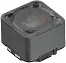 | 744871004 | SPEC Anstehende PCNAufgrund einer anstehenden PCN wird in Kürze eine Änderung am Bauteil durchgeführt. Anbei finden Sie die entsprechende PCN. Bei weiteren Fragen wenden Sie sich bitte an Ihren Vertriebsmitarbeiter. | 9 Dateien | Aktiv i| Produktion ist aktiv. Erwartete Lebenszeit: >10 Jahre. | WE-DD SMT-Doppeldrossel | – | – | – | – | – | – | – | – | – | – | -40 °C up to +125 °C | – | – | – | 12.5 | 12.5 | 6.5 | – | – | 4.7 | 3000 | 8 | – | – | – | – | – | – | – | – | – | – | – | – | – | – | – | 3000 | 0.028 | Gekreuzt | 4.7 | 4.7 | 3000 | 8 | 0.023 | 0.023 | 0.028 | 0.028 | 20 | – | 1260 | – | – | – | – | – | – | – | – | – | 20 | – | – | – | ||
| 885012108021 | SPEC | 9 Dateien | Aktiv i| Produktion ist aktiv. Erwartete Lebenszeit: >10 Jahre. | WCAP-CSGP MLCCs 25 V(DC) | – | – | – | – | – | – | – | 10 µF | ±20% | 25 | -55 °C up to +85 °C | 10 | 0.01 GΩ | X5R Klasse II | 3.2 | 1.6 | 1.6 | 0.6 | 7" Tape & Reel | – | – | – | – | – | – | – | – | – | – | – | – | – | – | – | – | – | – | – | – | – | – | – | – | – | – | – | – | – | – | – | 1206 | – | – | – | – | – | – | – | – | – | – | – | – | – | |||
| 885012109014 | SPEC | 9 Dateien | Aktiv i| Produktion ist aktiv. Erwartete Lebenszeit: >10 Jahre. | WCAP-CSGP MLCCs 25 V(DC) | – | – | – | – | – | – | – | 22 µF | ±20% | 25 | -55 °C up to +85 °C | 10 | 0.005 GΩ | X5R Klasse II | 3.2 | 2.5 | 2.5 | 0.6 | 7" Tape & Reel | – | – | – | – | – | – | – | – | – | – | – | – | – | – | – | – | – | – | – | – | – | – | – | – | – | – | – | – | – | – | – | 1210 | – | – | – | – | – | – | – | – | – | – | – | – | – | |||
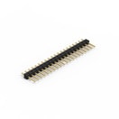 | 61302011121 | SPEC | – | 7 Dateien | Aktiv i| Produktion ist aktiv. Erwartete Lebenszeit: >10 Jahre. | WR-PHD Pin Header - Single | – | – | – | – | – | – | – | – | – | – | -40 °C up to +105 °C | – | 1000 MΩ | – | 50.8 | – | – | – | Beutel | – | 3000 | – | – | – | – | – | Stiftleiste | 20 | THT | – | 250 | 2.54 | Single | – | – | – | – | – | – | Gerade | – | – | – | – | – | – | – | – | – | – | – | – | – | – | – | – | – | – | – | – | – | – | – | – | |
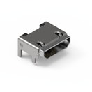 | 629105150521 | SPEC | – | 6 Dateien | Aktiv i| Produktion ist aktiv. Erwartete Lebenszeit: >10 Jahre. | WR-USB Mini/Micro Connectors | – | – | – | – | – | – | – | – | – | – | -40 °C up to +85 °C | – | 1000 MΩ | – | – | – | – | – | Tape and Reel | – | 3000 | – | – | Micro USB 2.0 | Type B | Mit Pegs- High Current | Buchse | 5 | SMT | 3000 | 30 | – | – | – | – | – | – | – | – | Horizontal | – | – | – | – | – | – | – | – | – | – | – | – | – | – | – | – | – | – | – | – | – | – | – | – | |
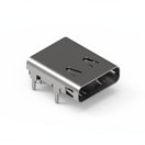 | 632723300011 | SPEC | – | 6 Dateien | Aktiv i| Produktion ist aktiv. Erwartete Lebenszeit: >10 Jahre. | WR-USB Type C Connectors | – | – | – | – | – | – | – | – | – | – | -40 °C up to +105 °C | – | 1000 MΩ | – | – | – | – | – | Tape and Reel | – | 5000 | – | – | USB 3.1 | Type C | – | Buchse | 24 | THR | – | 48 | – | – | 1.9 | – | – | – | – | – | Horizontal | – | – | – | – | – | – | – | – | – | – | – | – | – | – | – | – | – | – | – | – | – | – | – | – | |
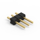 | 61300311121 | SPEC | – | 7 Dateien | Aktiv i| Produktion ist aktiv. Erwartete Lebenszeit: >10 Jahre. | WR-PHD Pin Header - Single | – | – | – | – | – | – | – | – | – | – | -40 °C up to +105 °C | – | 1000 MΩ | – | 7.62 | – | – | – | Beutel | – | 3000 | – | – | – | – | – | Stiftleiste | 3 | THT | – | 250 | 2.54 | Single | – | – | – | – | – | – | Gerade | – | – | – | – | – | – | – | – | – | – | – | – | – | – | – | – | – | – | – | – | – | – | – | – | |
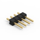 | 61300411121 | SPEC | – | 7 Dateien | Aktiv i| Produktion ist aktiv. Erwartete Lebenszeit: >10 Jahre. | WR-PHD Pin Header - Single | – | – | – | – | – | – | – | – | – | – | -40 °C up to +105 °C | – | 1000 MΩ | – | 10.16 | – | – | – | Beutel | – | 3000 | – | – | – | – | – | Stiftleiste | 4 | THT | – | 250 | 2.54 | Single | – | – | – | – | – | – | Gerade | – | – | – | – | – | – | – | – | – | – | – | – | – | – | – | – | – | – | – | – | – | – | – | – | |
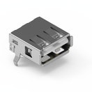 | 61400416021 | SPEC | – | 6 Dateien | Aktiv i| Produktion ist aktiv. Erwartete Lebenszeit: >10 Jahre. | WR-USB Standard Connectors | – | – | – | – | – | – | – | – | – | – | -40 °C up to +105 °C | – | 1000 MΩ | – | – | – | – | – | Tray | – | 1500 | – | – | USB 2.0 | Type A | – | Buchse | 4 | THT | 1500 | 30 | – | – | – | – | – | – | – | – | Horizontal | – | – | – | – | – | – | – | – | – | – | – | – | – | – | – | – | – | – | – | – | – | – | – | – | |
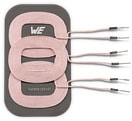 | 760308103147 | SPEC | 8 Dateien | Aktiv i| Produktion ist aktiv. Erwartete Lebenszeit: >10 Jahre. | WE-WPCC Wireless Power Array | – | – | – | – | – | – | – | – | – | – | -20 °C up to +105 °C | – | – | – | 100 | 55 | 5.2 | – | – | – | – | – | – | – | – | – | – | – | THT | 9000 | – | – | – | – | – | – | – | – | – | – | – | – | – | 18 | – | – | – | – | – | MP-A8 3-coil array | 100 x 55 x 5.2 mm | 8.5 | 7.5 | 8.5 | 9 | 10 | 9 | 0.056 | 56 | 56 | 11 | 11 | 11 | 150 |
| Artikel Nr. | Datenblatt | Simulation | |
|---|---|---|---|
 | 155124VS73200 | SPEC | |
 | 155124RS73200 | SPEC | |
 | 74279262 | SPEC | |
 | 74404054022 | SPEC | |
 | 744871004 | SPEC Anstehende PCNAufgrund einer anstehenden PCN wird in Kürze eine Änderung am Bauteil durchgeführt. Anbei finden Sie die entsprechende PCN. Bei weiteren Fragen wenden Sie sich bitte an Ihren Vertriebsmitarbeiter. | |
| 885012108021 | SPEC | ||
| 885012109014 | SPEC | ||
 | 61302011121 | SPEC | – |
 | 629105150521 | SPEC | – |
 | 632723300011 | SPEC | – |
 | 61300311121 | SPEC | – |
 | 61300411121 | SPEC | – |
 | 61400416021 | SPEC | – |
 | 760308103147 | SPEC |
| Muster |
|---|
| Artikel Nr. | Datenblatt | Simulation | Downloads | Status | Produktserie | λDom typ. (nm) | Farbe | λPeak typ. (nm) | IV typ. (mcd) | VF typ. (V) | Chiptechnologie | 2θ50% typ. (°) | C | Tol. C | VR (V (DC)) | Betriebstemperatur | DF (%) | RISO | Keramiktyp | L (mm) | W (mm) | H (mm) | Fl (mm) | Verpackung | L (µH) | IR (mA) | ISAT (A) | RDC (mΩ) | Anwendung | Interface typ | Ausführung | Gender | Pins (pcs) | Montageart | IR 1 (mA) | Arbeitsspannung (V (AC)) | Raster (mm) | Reihen | G (mm) | Z @ 100 MHz (Ω) | Zmax (Ω) | Testbedingung Zmax | IR 2 (mA) | RDC max. (Ω) | Typ | L1 (µH) | L2 (µH) | IR 1 (mA) | ISAT 1 (A) | RDC1 typ (Ω) | RDC2 typ (Ω) | RDC1 max (Ω) | RDC2 max (Ω) | fres (MHz) | Compliance | Bauform | L1 (µH) | L2 (µH) | L3 (µH) | IR DC1 (A) | IR DC2 (A) | IR DC3 (A) | RDC1 max. (Ω) | RDC2 max. (mΩ) | RDC3 max. (mΩ) | fres 1 (MHz) | fres 2 (MHz) | fres 3 (MHz) | P (W) | Muster |
|---|


