Texas Instruments LMG5200 | Demoboard TIDA-00909
48-V, 10-A, High-Frequency PWM, 3-Phase GaN Inverter Reference Design for High-Speed Motor Drives
Details
| Topologie | Gegentaktwandler (Halbbrücken) |
| Eingangsspannung | 12-60 V |
| Schaltfrequenz | 40-100 kHz |
| Ausgang 1 | 7 A |
| IC-Revision | A |
Beschreibung
Low-voltage, high-speed drives and low-inductancebrushless motors require higher inverter switchingfrequencies in the range of 40 kHz to 100 kHz tominimize losses and torque ripple in the motor. TheTIDA-00909 reference design achieves this by using athree-phase inverter with three 80 V, 10-A half-bridgeGaN power modules (LMG5200) and uses shuntbasedphase-current sensing. Gallium nitride (GaN)transistors can switch much faster than silicon fieldeffecttransistors (FETs) and integrating the GaN FETand driver in the same package reduces parasiticinductances and optimizes switching performance toreduce losses, thus allowing the designer to downsizeor eliminate the heatsink. The TIDA-00909 offers a TIBoosterPack™ Plug-in Module with a compatibleinterface to connect to a C2000™ MCU LaunchPad™Development Kit for easy performance evaluation.
Eigenschaften
- Three-Phase GaN Inverter With Wide-Input VoltageRange 12 V to 60 V and 7 ARMS per 10-A PeakOutput Current; Tested up to 100-kHz PWM
- GaN Power Stage With Greatly-Reduced SwitchingLosses Allows High PWM Switching FrequenciesWith Peak Efficiency up to 98.5% at 100-kHz PWM
- LMG5200 GaN Half-Bridge Power Stage SimplifiesPCB Layout and Reduces Parasitic Inductances forOptimized Switching Performance; Less than 2-nsRise and Fall Time
- Very-Low Switch Node Voltage Overshoot andUndershoot With Very-Low 12.5-ns DeadbandMinimizes Phase-Voltage Ringing and reducesPhase-Voltage Distortions and EMI
- Precision Shunt-Based, Phase-Current SensingWith High Accuracy (0.1%)
- TI BoosterPack™ Compatible Interface With 3.3-VI/O for Easy Performance Evaluation With C2000™MCU LaunchPad™ Development Kit
Typische Anwendungen
- Servo Drives and Motion Control,Manufacturing Robots,Service Robots,Non-Military Drones
- Computer Numerical Control (CNC) Drives
Weiterführende Informationen
Artikeldaten
| Artikel Nr. | Datenblatt | Simulation | Downloads | Status | Produktserie | λDom typ. (nm) | Farbe | λPeak typ. (nm) | IV typ. (mcd) | VF typ. (V) | Chiptechnologie | 2θ50% typ. (°) | C | Tol. C | VR (V (DC)) | Bauform | Betriebstemperatur | DF (%) | RISO | Keramiktyp | L (mm) | W (mm) | Fl (mm) | Verpackung | L (µH) | ISAT,10% (A) | ISAT,30% (A) | IR,40K (A) | IRP,40K (A) | fres (MHz) | Version | Z @ 100 MHz (Ω) | Zmax (Ω) | Testbedingung Zmax | IR 2 (mA) | RDC max. (Ω) | Typ | IR (mA) | Z @ 1 GHz (Ω) | H (mm) | Pins (pcs) | Anwendung | PCB/Kabel/Panel | Modularity | Wire Section | Muster | |
|---|---|---|---|---|---|---|---|---|---|---|---|---|---|---|---|---|---|---|---|---|---|---|---|---|---|---|---|---|---|---|---|---|---|---|---|---|---|---|---|---|---|---|---|---|---|---|---|
 | 150060GS75000 | SPEC | 26 Dateien Strahldaten
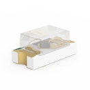
| Aktiv i| Produktion ist aktiv. Erwartete Lebenszeit: >10 Jahre. | WL-SMCW SMT Mono-color Chip LED Waterclear | 525 | Grün | 515 | 430 | 3.2 | InGaN | 140 | – | – | – | 0603 | -40 °C up to +85 °C | – | – | – | 1.6 | 0.8 | – | Tape and Reel | – | – | – | – | – | – | – | – | – | – | – | – | – | – | – | 0.7 | – | – | – | – | – | ||
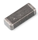
 | 74279272 | SPEC | 9 Dateien | Aktiv i| Produktion ist aktiv. Erwartete Lebenszeit: >10 Jahre. | WE-CBF SMT-Ferrit | – | – | – | – | – | – | – | – | – | – | 0402 | -55 °C up to +125 °C | – | – | – | 1 | 0.5 | 0.25 | – | – | – | – | – | – | – | SMT | 300 | 400 | 380 MHz | 700 | 0.8 | Breitband | 200 | 316 | 0.5 | – | – | – | – | – | ||
 | 74279223560 | SPEC | 10 Dateien | Aktiv i| Produktion ist aktiv. Erwartete Lebenszeit: >10 Jahre. | WE-MPSB EMI Multilayer Power Suppression Bead | – | – | – | – | – | – | – | – | – | – | 1612 | -55 °C up to +125 °C | – | – | – | 4.06 | 3.05 | 0.89 | – | – | – | – | – | – | – | SMT | 56 | 90 | 1000 MHz | 10000 | 0.004 | Hochstrom | 10000 | 90 | 2.28 | – | – | – | – | – | ||
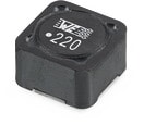
 | 7447709471 | SPEC | 9 Dateien | Aktiv i| Produktion ist aktiv. Erwartete Lebenszeit: >10 Jahre. | WE-PD Speicherdrossel | – | – | – | – | – | – | – | – | – | – | 1210 | -40 °C up to +125 °C | – | – | – | 12 | 12 | – | – | 470 | 1.5 | 1.85 | 1.4 | 1.45 | 1.8 | Gestanzt | – | – | – | – | 0.56 | – | 1400 | – | 10 | 2 | – | – | – | – | ||
| 885012206036 | SPEC | 9 Dateien | Aktiv i| Produktion ist aktiv. Erwartete Lebenszeit: >10 Jahre. | WCAP-CSGP MLCCs 16 V(DC) | – | – | – | – | – | – | – | 2.2 nF | ±10% | 16 | 0603 | -55 °C up to +125 °C | 3.5 | 10 GΩ | X7R Klasse II | 1.6 | 0.8 | 0.4 | 7" Tape & Reel | – | – | – | – | – | – | – | – | – | – | – | – | – | – | – | 0.8 | – | – | – | – | – | |||
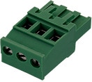
 | 691352510002 | SPEC | – | 3 Dateien | Aktiv i| Produktion ist aktiv. Erwartete Lebenszeit: >10 Jahre. | WR-TBL Serie 352 - 5.08 mm Horizontal with Hook on Wire Side | – | – | – | – | – | – | – | – | – | – | – | -40 °C up to +105 °C | – | – | – | 10.16 | – | – | Karton | – | – | – | – | – | – | – | – | – | – | – | – | Horizontal | 17000 | – | – | 2 | Steckbar | Kabel | Nein | 12 to 24 (AWG) 3.31 to 0.205 (mm²) |
| Artikel Nr. | Datenblatt | Simulation | |
|---|---|---|---|
 | 150060GS75000 | SPEC | |
 | 74279272 | SPEC | |
 | 74279223560 | SPEC | |
 | 7447709471 | SPEC | |
| 885012206036 | SPEC | ||
 | 691352510002 | SPEC | – |
| Muster |
|---|
| Artikel Nr. | Datenblatt | Simulation | Downloads | Status | Produktserie | λDom typ. (nm) | Farbe | λPeak typ. (nm) | IV typ. (mcd) | VF typ. (V) | Chiptechnologie | 2θ50% typ. (°) | C | Tol. C | VR (V (DC)) | Bauform | Betriebstemperatur | DF (%) | RISO | Keramiktyp | L (mm) | W (mm) | Fl (mm) | Verpackung | L (µH) | ISAT,10% (A) | ISAT,30% (A) | IR,40K (A) | IRP,40K (A) | fres (MHz) | Version | Z @ 100 MHz (Ω) | Zmax (Ω) | Testbedingung Zmax | IR 2 (mA) | RDC max. (Ω) | Typ | IR (mA) | Z @ 1 GHz (Ω) | H (mm) | Pins (pcs) | Anwendung | PCB/Kabel/Panel | Modularity | Wire Section | Muster |
|---|


