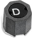
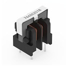
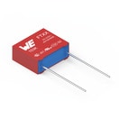
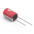
Details
| Topologie | Sperrwandler |
| Eingangsspannung | 85-265 V |
| Ausgang 1 | 12 V / 0.6 A |
Beschreibung
The varistor R4 together with resistor R3 form simple protection that enhances application robustness against line over−voltage and voltage spikes. Resistor R3 also limits theinrush current when the power supply is connected to mains.The EMC filter is implemented to reduce conducted electromagnetic emissions to the mains.The Flyback converter itself is formed by the high voltage switching regulator IC1, transformer TR1, freewheeling diode D3 and coil L1 (L3). Capacitors C5, C6, C7 and C8 areused as the output filtering and energy storage bank. Resistor R1 and capacitor C2 for filter, C1, R2 and D2 are forming voltage clamp for the switcher drain. Opto−coupler OK1(NCP431) is used in feedback network. Resistors R8, R12 and R13 form resistive divider and sets output voltage. Diode D7 and resistor R14 provide supply voltage for IC1Vcc from auxiliary winding. The capacitor C10 is the energy storage element that keeps IC1 powered during light load conditions, when the switching frequency drops and energyfrom auxiliary winding refills Vcc capacitors less often. Pin LIM/OPP is connected through resistor R6 to auxiliary winding and sets over−power protection. Resistor R9 decreases maximal peak current. The frequencycompensation of the feedback loop system is ensured by external capacitor C8 that is connected to the IC OTA output.
Eigenschaften
- Universal AC Input Range (85 – 265 Vac)
- Input Filter for Conducted EMI Attenuation
- Very Low Standby and No−load Power Consumption
- Frequency Fold−back for Improved Efficiency at Light Load
- Inherent Over−current, Over−voltage andOver−temperature Protections
- Frequency Jittering for Better EMI Signature
- Adjustable Peak Current to Set the Required Level of Over−current Protection
Weiterführende Informationen
Artikeldaten
| Artikel Nr. | Datenblatt | Simulation | Downloads | Status | Produktserie | Pins (pcs) | Anwendung | PCB/Kabel/Panel | Modularity | Typ | Wire Section | C | Sicherheitsklasse | dV/dt (V/µs) | DF @ 1 kHz (%) | RISO | Raster (mm) | Verpackung | ISAT (A) | fres (MHz) | Endurance (h) | IRIPPLE (mA) | ILeak (µA) | DF (%) | Ø D (mm) | RESR (mΩ) | Vin | VOut1 (V) | IOut1 (mA) | VOut2 (V) | IOut2 (mA) | Vaux (V) | fswitch (kHz) | NPRI : NSEC : NAUX | Bauform | IR (A) | L (µH) | RDC max. (mΩ) | VR (V (AC)) | VT (V (AC)) | Material | L (mm) | W (mm) | H (mm) | Montageart | VRMS (V) | VDC (V) | VBR (V) | IPeak (A) | Wmax (J) | PDiss (W) | VDE-Zulassung | Muster | |
|---|---|---|---|---|---|---|---|---|---|---|---|---|---|---|---|---|---|---|---|---|---|---|---|---|---|---|---|---|---|---|---|---|---|---|---|---|---|---|---|---|---|---|---|---|---|---|---|---|---|---|---|---|---|---|
 | 744025002 | SPEC | 9 Dateien | Aktiv i| Produktion ist aktiv. Erwartete Lebenszeit: >10 Jahre. | WE-TPC SMT-Speicherdrossel | 2 | – | – | – | – | – | – | – | – | – | – | – | – | 2.4 | 130 | – | – | – | – | – | – | – | – | – | – | – | – | – | – | 2828 | 1.8 | 2.2 | 66 | – | – | – | 2.8 | 2.8 | 2.8 | SMT | – | – | – | – | – | – | – | ||
 | 691101710002 | SPEC | – | 6 Dateien | Aktiv i| Produktion ist aktiv. Erwartete Lebenszeit: >10 Jahre. | WR-TBL Series 101 - 5.00 mm Horizontal Entry Modular | 2 | Kabelschutzprinzip | PCB | Ja | Horizontal | 26 to 14 (AWG) 0.5 to 2.5 (mm²) | – | – | – | – | – | 5 | Karton | – | – | – | – | – | – | – | – | – | – | – | – | – | – | – | – | – | 16 | – | – | – | – | – | 10 | – | 12.6 | THT | – | – | – | – | – | – | 40022614 | |
 | 744862120 | SPEC | 10 Dateien | Aktiv i| Produktion ist aktiv. Erwartete Lebenszeit: >10 Jahre. | WE-TFC Stromkompensierte Netzdrossel | 4 | – | – | – | – | – | – | – | – | – | – | – | – | – | – | – | – | – | – | – | – | – | – | – | – | – | – | – | – | UU 9.8 V | 0.4 | 12000 | 2000 | 300 | 2500 | MnZn | 17 | 11.5 | 17 | THT | – | – | – | – | – | – | – | ||
 | 820572711 | SPEC | 7 Dateien | Aktiv i| Produktion ist aktiv. Erwartete Lebenszeit: >10 Jahre. | WE-VD Disk Varistor | – | 230 VAC | – | – | – | – | – | – | – | – | – | – | – | – | – | – | – | – | – | 9 | – | – | – | – | – | – | – | – | – | 7 mm | – | – | – | – | – | – | 9 | 3.9 | 12.5 | THT | 275 | 350 | 430 | 1200 | 33 | 0.25 | Ja | ||
 | 890334025013CS | SPEC | 9 Dateien | Aktiv i| Produktion ist aktiv. Erwartete Lebenszeit: >10 Jahre. | WCAP-FTXX Folienkondensatoren | – | Across the mains | – | – | – | – | 68 nF | X2 | 270 | 0.1 | 30 GΩ | 15 | Karton | – | – | – | – | – | – | – | – | – | – | – | – | – | – | – | – | Raster 15 mm | – | – | – | 310 | – | – | 18 | 6 | 12 | Boxed THT | – | – | – | – | – | – | – | ||
 | 890334025022 | SPEC | 9 Dateien | Aktiv i| Produktion ist aktiv. Erwartete Lebenszeit: >10 Jahre. | WCAP-FTXX Folienkondensatoren | – | Across the mains | – | – | – | – | 150 nF | X2 | 210 | 0.1 | 30 GΩ | 15 | Lose | – | – | – | – | – | – | – | – | – | – | – | – | – | – | – | – | Raster 15 mm | – | – | – | 310 | – | – | 18 | 6 | 12 | Boxed THT | – | – | – | – | – | – | – | ||
 | 768772102 | SPEC | 9 Dateien | Aktiv i| Produktion ist aktiv. Erwartete Lebenszeit: >10 Jahre. | WE-TI HV Tonneninduktivität (High Voltage) | – | – | – | – | – | – | – | – | – | – | – | – | – | 0.55 | 1.8 | – | – | – | – | – | – | – | – | – | – | – | – | – | – | 8095 | 0.5 | 1000 | 2080 | – | – | NiZn | 7.8 | 7.8 | 9.5 | THT | – | – | – | – | – | – | – | ||
 | 860010572001 | SPEC | 8 Dateien | Aktiv i| Produktion ist aktiv. Erwartete Lebenszeit: >10 Jahre. | WCAP-ATG8 Aluminium-Elektrolytkondensatoren | – | – | – | – | – | – | 4.7 µF | – | – | – | – | 2 | Ammopack | – | – | 2000 | 44 | 3 | 12 | 5 | – | – | – | – | – | – | – | – | – | – | – | – | – | 35 | – | – | 11 | – | – | – | – | – | – | – | – | – | – | ||
 | 860011375006 | SPEC | 8 Dateien | Aktiv i| Produktion ist aktiv. Erwartete Lebenszeit: >10 Jahre. | WCAP-ATG8 Aluminium-Elektrolytkondensatoren | – | – | – | – | – | – | 10 µF | – | – | – | – | 5 | Ammopack | – | – | 2000 | 100 | 120 | 15 | 10 | – | – | – | – | – | – | – | – | – | – | – | – | – | 400 | – | – | 16 | – | – | – | – | – | – | – | – | – | – | ||
 | 870055673001 | SPEC | 8 Dateien | Aktiv i| Produktion ist aktiv. Erwartete Lebenszeit: >10 Jahre. | WCAP-PTHR Aluminium-Polymer-Kondensatoren | – | – | – | – | – | – | 10 µF | – | – | – | – | 2.5 | Ammopack | – | – | 2000 | 2100 | 100 | 12 | 6.3 | 40 | – | – | – | – | – | – | – | – | – | – | – | – | 35 | – | – | 8 | – | – | Radial THT | – | – | – | – | – | – | – | ||
 | 870235375008 | SPEC | 8 Dateien | Aktiv i| Produktion ist aktiv. Erwartete Lebenszeit: >10 Jahre. | WCAP-PT5H Aluminium-Polymer-Kondensatoren | – | – | – | – | – | – | 470 µF | – | – | – | – | 5 | Ammopack | – | – | 5000 | 6100 | 752 | 10 | 10 | 9 | – | – | – | – | – | – | – | – | – | – | – | – | 16 | – | – | 12.5 | – | – | Radial THT | – | – | – | – | – | – | – | ||
 | 750370026 | SPEC | 10 Dateien | Aktiv i| Produktion ist aktiv. Erwartete Lebenszeit: >10 Jahre. | WE-OLSTM Offline Flyback Transformers | – | – | – | – | – | – | – | – | – | – | – | – | Tray | 0.44 | – | – | – | – | – | – | – | 85 - 272 V (AC) | 12 | 300 | 12 | 300 | 12 | 70 - 134 | 8.96:1:1:1 | EE16/8/5 | – | 3900 | – | – | 3200 | – | 20.2 | 24.2 | 15.5 | THT | – | – | – | – | – | – | – |
| Muster |
|---|
| Artikel Nr. | Datenblatt | Simulation | Downloads | Status | Produktserie | Pins (pcs) | Anwendung | PCB/Kabel/Panel | Modularity | Typ | Wire Section | C | Sicherheitsklasse | dV/dt (V/µs) | DF @ 1 kHz (%) | RISO | Raster (mm) | Verpackung | ISAT (A) | fres (MHz) | Endurance (h) | IRIPPLE (mA) | ILeak (µA) | DF (%) | Ø D (mm) | RESR (mΩ) | Vin | VOut1 (V) | IOut1 (mA) | VOut2 (V) | IOut2 (mA) | Vaux (V) | fswitch (kHz) | NPRI : NSEC : NAUX | Bauform | IR (A) | L (µH) | RDC max. (mΩ) | VR (V (AC)) | VT (V (AC)) | Material | L (mm) | W (mm) | H (mm) | Montageart | VRMS (V) | VDC (V) | VBR (V) | IPeak (A) | Wmax (J) | PDiss (W) | VDE-Zulassung | Muster |
|---|


