Details
| Topologie | Sonstige Topologie |
| Eingangsspannung | 200-400 V |
| Ausgang 1 | 380 V / 40 A |
| IC-Revision | 1.0.1 |
Beschreibung
This document is the entry point to the reference documentation of PTC heater discrete IGBT driver board evaluation platform, version 1.0.1. The evaluation platform is for thermal performance evaluation that provides developers with the tools and test data needed to build applications that drive PTC based on high current isolated driver and IGBT from On Semiconductor. This documentation focuses on the output voltage and current adjustment through high side and low side IGBT, and would help user to setup different variables, such as voltage, to get the wanted current and get the wanted test condition. Finally, it will help customer better understand isolated driver and IGBT performance by tested data and curve.
Eigenschaften
- 4V to 16V Operating Input Range
- Wide Output Voltage:
- I2C Programmable: 0.55V to 5.4V
- External Resistor Divider: 0.6V to 7V or VIN * DMAX if VIN < 7V
- Channel 1 and 2: 3A Continuous Current
- Channel 3 and 4: 2A Continuous Current
- Interleaved Operation
- Configurable, Multi-Functional GPIO Pin
- I2C and Configurable Parameters:
- Paralleling Channel 1 and 2
- Paralleling Channel 3 and 4
- Switching Frequency
- Output Voltage
- Over-Current and Over-Voltage Protection Threshold
- Power-On and Power-Off Sequencing
- Forced PWM or Auto-PWM/PFM
- Preset to MPM54304GMN-0000 Configuration
Weiterführende Informationen
Artikeldaten
| Artikel Nr. | Datenblatt | Simulation | Downloads | Status | Produktserie | C | dV/dt (V/µs) | DF @ 1 kHz (%) | RISO | Raster (mm) | Verpackung | IRP,40K (A) | ISAT,10% (A) | ISAT,30% (A) | fres (MHz) | Endurance (h) | IRIPPLE (mA) | ILeak (µA) | DF (%) | Ø D (mm) | Z (mΩ) | IR (A) | L (µH) | RDC max. (mΩ) | VR (V (DC)) | VT (V (AC)) | Material | L (mm) | W (mm) | H (mm) | Montageart | Muster | |
|---|---|---|---|---|---|---|---|---|---|---|---|---|---|---|---|---|---|---|---|---|---|---|---|---|---|---|---|---|---|---|---|---|---|
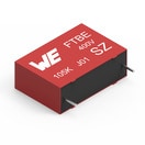
 | 890303423005CS | SPEC | 9 Dateien | Aktiv i| Produktion ist aktiv. Erwartete Lebenszeit: >10 Jahre. | WCAP-FTBE Folienkondensatoren | 68 nF | 52 | 1 | 9000 MΩ | 10 | Karton | – | – | – | – | – | – | – | – | – | – | – | – | – | 630 | – | – | 13 | 5.5 | 11 | – | ||
 | 865060542002 | SPEC | 9 Dateien | Aktiv i| Produktion ist aktiv. Erwartete Lebenszeit: >10 Jahre. | WCAP-ASLL Aluminium-Elektrolytkondensatoren | 10 µF | – | – | 10 MΩ | – | 15" Tape & Reel | – | – | – | – | 2000 | 150 | 3.5 | 14 | 5 | 800 | – | – | – | 35 | – | – | 5.5 | 5.3 | – | V-Chip SMT | ||
 | 865090240001 | SPEC | 9 Dateien | Aktiv i| Produktion ist aktiv. Erwartete Lebenszeit: >10 Jahre. | WCAP-ASLU Aluminium-Elektrolytkondensatoren | 10 µF | – | – | 3.33333 MΩ | – | 15" Tape & Reel | – | – | – | – | 1000 | 23 | 0.4 | 22 | 4 | – | – | – | – | 10 | – | – | 5.5 | 4.3 | – | V-Chip SMT | ||
 | 860241478004 | SPEC | 7 Dateien | Aktiv i| Produktion ist aktiv. Erwartete Lebenszeit: >10 Jahre. | WCAP-AT1H Aluminium-Elektrolytkondensatoren | 22 µF | – | – | – | 5 | Ammopack | – | – | – | – | 10000 | 632 | 496 | 20 | 13 | – | – | – | – | 450 | – | – | 25 | – | – | – | ||
 | 865090545008 | SPEC | 9 Dateien | Aktiv i| Produktion ist aktiv. Erwartete Lebenszeit: >10 Jahre. | WCAP-ASLU Aluminium-Elektrolytkondensatoren | 47 µF | – | – | 2.12766 MΩ | – | 15" Tape & Reel | – | – | – | – | 1000 | 75 | 3.3 | 14 | 6.3 | – | – | – | – | 35 | – | – | 7.7 | 6.6 | – | V-Chip SMT | ||
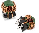
 | 7448421016 | SPEC | 9 Dateien | Aktiv i| Produktion ist aktiv. Erwartete Lebenszeit: >10 Jahre. | WE-CMB NiZn Stromkompensierte Netzdrossel | – | – | – | – | – | – | – | – | – | – | – | – | – | – | – | – | 10 | 16 | 3 | 250 | 1500 | NiZn | 18.5 | 14.5 | 22 | THT | ||
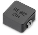
 | 74437346015 | SPEC | 9 Dateien | Aktiv i| Produktion ist aktiv. Erwartete Lebenszeit: >10 Jahre. | WE-LHMI SMT Speicherdrossel | – | – | – | – | – | – | 9.1 | 11.2 | 27.6 | 45 | – | – | – | – | – | – | – | 1.5 | 15 | – | – | – | 7.3 | 6.6 | 2.8 | SMT | ||
 | 74437377033 | SPEC | 9 Dateien | Aktiv i| Produktion ist aktiv. Erwartete Lebenszeit: >10 Jahre. | WE-LHMI SMT Speicherdrossel | – | – | – | – | – | – | 12.8 | 13.3 | 30.9 | 17 | – | – | – | – | – | – | – | 3.3 | 11 | – | – | – | 13.5 | 12.6 | 3.3 | SMT |
| Artikel Nr. | Datenblatt | Simulation | |
|---|---|---|---|
 | 890303423005CS | SPEC | |
 | 865060542002 | SPEC | |
 | 865090240001 | SPEC | |
 | 860241478004 | SPEC | |
 | 865090545008 | SPEC | |
 | 7448421016 | SPEC | |
 | 74437346015 | SPEC | |
 | 74437377033 | SPEC |
| Muster |
|---|
| Artikel Nr. | Datenblatt | Simulation | Downloads | Status | Produktserie | C | dV/dt (V/µs) | DF @ 1 kHz (%) | RISO | Raster (mm) | Verpackung | IRP,40K (A) | ISAT,10% (A) | ISAT,30% (A) | fres (MHz) | Endurance (h) | IRIPPLE (mA) | ILeak (µA) | DF (%) | Ø D (mm) | Z (mΩ) | IR (A) | L (µH) | RDC max. (mΩ) | VR (V (DC)) | VT (V (AC)) | Material | L (mm) | W (mm) | H (mm) | Montageart | Muster |
|---|


