Details
| Topologie | Battery Management System |
| IC-Revision | 1 |
Beschreibung
The AEK-COM-ISOSPI1 is a SPI to isolated SPI dongle, which allows converting SPI signals in isolated SPI signals, thereby reducing the number of necessary wires from 4 to 2.The ISOSPI protocol features differential communication to ensure higher noise immunity and robustness for long distance communications. As the ISOSPI signals can travel for several meters, this protocol is particularly suitable for automotive high voltage applications where electrical isolation is required by the safety standards and the cable length can affect the communication among devices located in distant parts of the vehicle.The AEK-COM-ISOSPI1 is based on the L9963T general purpose SPI to isolated SPI bi-directional transceiver, which can transfer communication data incoming from a classical 4-wire based SPI interface to a 2-wire isolated interface (and vice versa).The L9963T hosted on the AEK-COM-ISOSPI1 can be configured either as a slave or as a master of the SPI bus and supports any protocol of 8-to-64-bit SPI frames. The SPI peripheral can work up to 10 MHz when configured as a slave. The SPI clock frequency can be programmed (250 kHz, 1 MHz, 4 MHz, or 8 MHz) when the device is configured as a master.The transceiver is natively compatible with the L9963E isolated SPI, allowing its usage in battery management system (BMS) applications. The basic BMS analog front-end node board is the AEK-POW-BMS63EN. From the microcontroller side, the AEK-COM-ISOSPI1 board can be connected via SPI with SPC5, Stellar and STM32 microcontroller families.In the AutoDevKit ecosystem software package, we created two example demos: SPC582B - ISOSPI1_LEDdriver test application for discovery, to be downloaded on an AEK-MCU-C1MLIT1 MCU board, and SPC58EC - ISOSPI1_LEDdriver test application for discovery, to be downloaded on an AEK-MCU-C4MLIT1 MCU board. The MCU board of both demos communicate with an AEK-LED-21DISM1 LED driver board using two AEK-COM-ISOSPI1 dongles.The aim of these demos is to show how to configure the AEK-COM-ISOSPI1 to allow the MCU board to communicate with the LED driver board via SPI protocol.After uploading the demos, the MCU boards can send a command to the LED driver board via SPI protocol through the first AEK-COM-ISOSPI1, which converts the SPI signal into an ISOSPI message and then transmits it to the second AEK-COM-ISOSPI1, which converts it back into a SPI message. Finally, the message is transmitted to the AEK-LED-21DISM1 LED driver that executes the command sent. The commands sent are related to the activation of the bucks and the reading of the status register of the AEK-LED-21DISM1 LED driver.
Typische Anwendungen
- SPI to isolated SPI dongle for Battery Management Systems (BMS)
- SPI to isolated SPI dongle for Battery Management Systems (BMS)
Weiterführende Informationen
Artikeldaten
| Artikel Nr. | Datenblatt | Simulation | Downloads | Status | Produktserie | λDom typ. (nm) | Farbe | λPeak typ. (nm) | IV typ. (mcd) | VF typ. (V) | Chiptechnologie | 2θ50% typ. (°) | Gender | Pins | Ausführung | Typ | Wire Section | Kontaktbeschichtung | IR (A) | Arbeitsspannung (V (AC)) | Kontaktwiderstand (mΩ) | Verpackung | VPE (pcs) | Stranded Wire Section (AWG) | Stranded Wire Section (Metric) | C | Tol. C | VR (V (DC)) | Bauform | Betriebstemperatur | Q (%) | DF (%) | RISO | Keramiktyp | L (mm) | W (mm) | H (mm) | Fl (mm) | Schlüsselweite (mm) | Ti | Brennbarkeitsklasse | Anwendung | Interface typ | Montageart | IR 1 (A) | Farbe | Raster (mm) | Reihen | PCB/Kabel/Panel | Tol. R | Muster | |
|---|---|---|---|---|---|---|---|---|---|---|---|---|---|---|---|---|---|---|---|---|---|---|---|---|---|---|---|---|---|---|---|---|---|---|---|---|---|---|---|---|---|---|---|---|---|---|---|---|---|---|---|---|
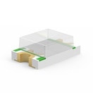 | 150080BS75000 | SPEC | 7 Dateien | Aktiv i| Produktion ist aktiv. Erwartete Lebenszeit: >10 Jahre. | WL-SMCW SMT Mono-color Chip LED Waterclear | 470 | Blau | 465 | 145 | 3.2 | InGaN | 140 | – | – | – | – | – | – | – | – | – | Tape and Reel | 4000 | – | – | – | – | – | 0805 | -40 °C up to +85 °C | – | – | – | – | 2 | 1.25 | 0.7 | – | – | – | – | – | – | SMT | – | – | – | – | – | – | ||
 | 150080GS75000 | SPEC | 7 Dateien | Aktiv i| Produktion ist aktiv. Erwartete Lebenszeit: >10 Jahre. | WL-SMCW SMT Mono-color Chip LED Waterclear | 525 | Grün | 515 | 450 | 3.2 | InGaN | 140 | – | – | – | – | – | – | – | – | – | Tape and Reel | 4000 | – | – | – | – | – | 0805 | -40 °C up to +85 °C | – | – | – | – | 2 | 1.25 | 0.7 | – | – | – | – | – | – | SMT | – | – | – | – | – | – | ||
 | 150080YS75000 | SPEC | 6 Dateien | Aktiv i| Produktion ist aktiv. Erwartete Lebenszeit: >10 Jahre. | WL-SMCW SMT Mono-color Chip LED Waterclear | 590 | Gelb | 595 | 120 | 2 | AlInGaP | 140 | – | – | – | – | – | – | – | – | – | Tape and Reel | 4000 | – | – | – | – | – | 0805 | -40 °C up to +85 °C | – | – | – | – | 2 | 1.25 | 0.7 | – | – | – | – | – | – | SMT | – | – | – | – | – | – | ||
 | 150080AS75000 | SPEC | 7 Dateien | Aktiv i| Produktion ist aktiv. Erwartete Lebenszeit: >10 Jahre. | WL-SMCW SMT Mono-color Chip LED Waterclear | 605 | Bernstein | 610 | 130 | 2 | AlInGaP | 140 | – | – | – | – | – | – | – | – | – | Tape and Reel | 4000 | – | – | – | – | – | 0805 | -40 °C up to +85 °C | – | – | – | – | – | – | – | – | – | – | – | – | – | SMT | – | – | – | – | – | – | ||
 | 150080RS75000 | SPEC | 7 Dateien | Aktiv i| Produktion ist aktiv. Erwartete Lebenszeit: >10 Jahre. | WL-SMCW SMT Mono-color Chip LED Waterclear | 625 | Rot | 630 | 150 | 2 | AlInGaP | 140 | – | – | – | – | – | – | – | – | – | Tape and Reel | 4000 | – | – | – | – | – | 0805 | -40 °C up to +85 °C | – | – | – | – | 2 | 1.25 | 0.7 | – | – | – | – | – | – | SMT | – | – | – | – | – | – | ||
| 885012006053 | SPEC | 9 Dateien | Aktiv i| Produktion ist aktiv. Erwartete Lebenszeit: >10 Jahre. | WCAP-CSGP MLCCs 50 V(DC) | – | – | – | – | – | – | – | – | – | – | – | – | – | – | – | – | 7" Tape & Reel | 4000 | – | – | 22 pF | ±5% | 50 | 0603 | -55 °C up to +125 °C | 840 | – | 10 GΩ | NP0 Klasse I | 1.6 | 0.8 | 0.8 | 0.4 | – | – | – | – | – | – | – | – | – | – | – | – | |||
| 885012206089 | SPEC | 9 Dateien | Aktiv i| Produktion ist aktiv. Erwartete Lebenszeit: >10 Jahre. | WCAP-CSGP MLCCs 50 V(DC) | – | – | – | – | – | – | – | – | – | – | – | – | – | – | – | – | 7" Tape & Reel | 4000 | – | – | 10 nF | ±10% | 50 | 0603 | -55 °C up to +125 °C | – | 2.5 | 10 GΩ | X7R Klasse II | 1.6 | 0.8 | 0.8 | 0.4 | – | – | – | – | – | – | – | – | – | – | – | – | |||
| 885012206095 | SPEC | 9 Dateien | Aktiv i| Produktion ist aktiv. Erwartete Lebenszeit: >10 Jahre. | WCAP-CSGP MLCCs 50 V(DC) | – | – | – | – | – | – | – | – | – | – | – | – | – | – | – | – | 7" Tape & Reel | 4000 | – | – | 100 nF | ±10% | 50 | 0603 | -55 °C up to +125 °C | – | 3 | 5 GΩ | X7R Klasse II | 1.6 | 0.8 | 0.8 | 0.4 | – | – | – | – | – | – | – | – | – | – | – | – | |||
| 885012207103 | SPEC | 9 Dateien | Aktiv i| Produktion ist aktiv. Erwartete Lebenszeit: >10 Jahre. | WCAP-CSGP MLCCs 50 V(DC) | – | – | – | – | – | – | – | – | – | – | – | – | – | – | – | – | 7" Tape & Reel | 3000 | – | – | 1 µF | ±10% | 50 | 0805 | -55 °C up to +125 °C | – | 10 | 0.1 GΩ | X7R Klasse II | 2 | 1.25 | 1.25 | 0.5 | – | – | – | – | – | – | – | – | – | – | – | – | |||
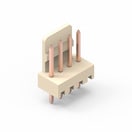 | 61900411121 | SPEC | – | 7 Dateien | Aktiv i| Produktion ist aktiv. Erwartete Lebenszeit: >10 Jahre. | WR-WTB 2.54 mm Male Header | – | – | – | – | – | – | – | Männlich | 4 | – | Vertikal | – | Zinn | 3 | 250 | 20 | Beutel | – | – | – | – | – | – | – | -40 °C up to +105 °C | – | – | 1000 MΩ | – | 10.16 | – | – | – | – | – | – | – | – | THT | – | – | 2.54 | – | PCB | max. | |
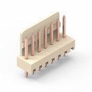 | 61900711121 | SPEC | – | 7 Dateien | Aktiv i| Produktion ist aktiv. Erwartete Lebenszeit: >10 Jahre. | WR-WTB 2.54 mm Male Header | – | – | – | – | – | – | – | Männlich | 7 | – | Vertikal | – | Zinn | 3 | 250 | 20 | Beutel | – | – | – | – | – | – | – | -40 °C up to +105 °C | – | – | 1000 MΩ | – | 17.78 | – | – | – | – | – | – | – | – | THT | 3 | Beige | 2.54 | – | PCB | max. | |
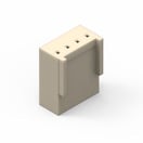 | 61900411621 | SPEC | – | 4 Dateien | Aktiv i| Produktion ist aktiv. Erwartete Lebenszeit: >10 Jahre. | WR-WTB 2.54 mm Female Terminal Housing | – | – | – | – | – | – | – | Weiblich | 4 | – | Klemmengehäuse | – | – | – | – | – | Beutel | – | – | – | – | – | – | – | -40 °C up to +105 °C | – | – | 1000 MΩ | – | 10.8 | – | – | – | – | – | – | – | – | – | – | Beige | 2.54 | – | Kabel | – | |
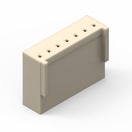 | 61900711621 | SPEC | – | 4 Dateien | Aktiv i| Produktion ist aktiv. Erwartete Lebenszeit: >10 Jahre. | WR-WTB 2.54 mm Female Terminal Housing | – | – | – | – | – | – | – | Weiblich | 7 | – | Klemmengehäuse | – | – | – | – | – | Beutel | – | – | – | – | – | – | – | -40 °C up to +105 °C | – | – | 1000 MΩ | – | 18.3 | – | – | – | – | – | – | – | – | – | – | Beige | 2.54 | – | Kabel | – | |
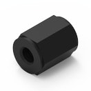 | 970080365 | SPEC | – | 3 Dateien | Aktiv i| Produktion ist aktiv. Erwartete Lebenszeit: >10 Jahre. | WA-SPAII Plastic Spacer Stud, metric, internal/ internal | – | – | – | – | – | – | – | – | – | – | – | – | – | – | – | – | Beutel | – | – | – | – | – | – | – | -30 °C up to +110 °C | – | – | – | – | 8 | – | – | – | 6 | M3 | UL94 HB | – | – | – | – | Schwarz | – | – | – | – | |
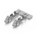 | 61910113722 | SPEC | – | 3 Dateien | Aktiv i| Produktion ist aktiv. Erwartete Lebenszeit: >10 Jahre. | WR-WTB 2.54 mm Female Crimp Contact | – | – | – | – | – | – | – | Weiblich | – | – | Crimpkontakt | 28 to 22 (AWG) 0.081 to 0.326 (mm²) | Zinn | 3 | 250 | 20 | kleine Rolle | 1000 | 28 to 22 (AWG) | 0.081 to 0.326 (mm²) | – | – | – | – | -40 °C up to +105 °C | – | – | – | – | – | – | – | – | – | – | – | – | – | – | 3 | – | 2.54 | – | Kabel | max. | |
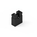 | 60900213421 | SPEC | – | 3 Dateien | Aktiv i| Produktion ist aktiv. Erwartete Lebenszeit: >10 Jahre. | WR-PHD Jumper | – | – | – | – | – | – | – | Jumper | 1 | – | – | – | Gold | 3 | 250 | 20 | Beutel | – | – | – | – | – | – | – | -40 °C up to +125 °C | – | – | 1000 MΩ | – | 2.44 | – | – | – | – | – | – | – | – | – | – | Schwarz | 2.54 | – | – | max. | |
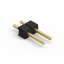 | 61300211121 | SPEC | – | 7 Dateien | Aktiv i| Produktion ist aktiv. Erwartete Lebenszeit: >10 Jahre. | WR-PHD Pin Header - Single | – | – | – | – | – | – | – | Stiftleiste | 2 | – | Gerade | – | Gold | 3 | 250 | 20 | Beutel | – | – | – | – | – | – | – | -40 °C up to +105 °C | – | – | 1000 MΩ | – | 5.08 | – | – | – | – | – | – | – | – | THT | – | – | 2.54 | Single | – | max. | |
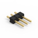 | 61300311121 | SPEC | – | 7 Dateien | Aktiv i| Produktion ist aktiv. Erwartete Lebenszeit: >10 Jahre. | WR-PHD Pin Header - Single | – | – | – | – | – | – | – | Stiftleiste | 3 | – | Gerade | – | Gold | 3 | 250 | 20 | Beutel | – | – | – | – | – | – | – | -40 °C up to +105 °C | – | – | 1000 MΩ | – | 7.62 | – | – | – | – | – | – | – | – | THT | – | – | 2.54 | Single | – | max. | |
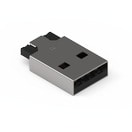 | 629004113921 | SPEC | – | 6 Dateien | Aktiv i| Produktion ist aktiv. Erwartete Lebenszeit: >10 Jahre. | WR-USB Standard Connectors | – | – | – | – | – | – | – | Stecker | 4 | Mit Clips | Horizontal | – | selektiv vergoldet | 1.5 | 30 | 20 | Tube | – | – | – | – | – | – | – | -40 °C up to +105 °C | – | – | 1000 MΩ | – | – | – | – | – | – | – | – | USB 2.0 | Type A | SMT | – | – | – | – | – | max. | |
 | 97790403111 | SPEC | – | 3 Dateien | Aktiv i| Produktion ist aktiv. Erwartete Lebenszeit: >10 Jahre. | WA-SCRW Linsenkopfschraube M3 mit Kreuzschlitz | – | – | – | – | – | – | – | – | – | – | – | – | – | – | – | – | Lose | 2000 | – | – | – | – | – | – | -30 °C up to +85 °C | – | – | – | – | 4 | – | – | – | – | – | UL94 V-2 | – | – | – | – | Natur | – | – | – | – |
| Muster |
|---|
| Artikel Nr. | Datenblatt | Simulation | Downloads | Status | Produktserie | λDom typ. (nm) | Farbe | λPeak typ. (nm) | IV typ. (mcd) | VF typ. (V) | Chiptechnologie | 2θ50% typ. (°) | Gender | Pins | Ausführung | Typ | Wire Section | Kontaktbeschichtung | IR (A) | Arbeitsspannung (V (AC)) | Kontaktwiderstand (mΩ) | Verpackung | VPE (pcs) | Stranded Wire Section (AWG) | Stranded Wire Section (Metric) | C | Tol. C | VR (V (DC)) | Bauform | Betriebstemperatur | Q (%) | DF (%) | RISO | Keramiktyp | L (mm) | W (mm) | H (mm) | Fl (mm) | Schlüsselweite (mm) | Ti | Brennbarkeitsklasse | Anwendung | Interface typ | Montageart | IR 1 (A) | Farbe | Raster (mm) | Reihen | PCB/Kabel/Panel | Tol. R | Muster |
|---|


