Analog Devices LTC3633 | Demoboard DC2619A
LTC2972 2-Channel PMBus Power System Manager with Eight Power Supply Rails
Overview
| Topology | Buck Converter |
| Input voltage | 12 V |
| Switching frequency | 500-4000 kHz |
| Output 1 | 5 V |
| IC revision | 1 |
Description
The DC2619A is a demonstration system for the LTC2972 power system manager that interfaces to various regulators. The board contains all the circuitry needed to demonstrate a power system that utilizes four 2-channel LTC2972 devices that manage eight power supplies. The eight power supplies include linear and switching regulators or the purpose of demonstrating a variety of methods to sense voltage and current. The demo board provides a sophisticated 8-channel programmable power supply system. The LTC2972 is a 2-channel I2C/SMBus/PMBus power system manager that features accurate input current and energy measurement. The device monitors input current and input voltage, and calculates input power and energy. The DC2619A demonstrates the ability of the LTC2972 to sequence, trim, margin, supervise, monitor, and log faults for eight power supplies. The LTC2972 monitors each channel’s output voltage and output current and also monitors external temperature sensors and its own internal die temperature.The DC2619A board contains eight independent power supply rails. The +5V/–5V rails are based on the switched capacitor LTC3260 regulator, the 1.0V/1.2V rails are powered by an LTC3633 switching regulator, the 1.5V/1.8V rails are powered by LTC3405A switching regulators, and the 2.5/3.3V rails are powered by LT3086/LT3055 linear regulators. The board is pre-configured with these voltages and may be re-configured with feedback resistors.The LTpowerPlay® graphical user interface (GUI) supports this demonstration system and enables complete control of all the features of the LTC2972. Together, the LTpowerPlay software and DC2619A hardware system create a powerful development environment for designing and testing configuration settings of the LTC2972. LTpowerPlay stores these settings in the LTC2972’s internal EEPROM or in a project file. The software displays all of the configuration settings and real time measurements from the power system management IC. Telemetry allows easy access and decoding of the fault log created by the LTC2972. The board comes preprogrammed with the EEPROM values appropriate for the eight power supply rails on the DC2619A. Just plug and play!
Features
- Sequence, Trim, Margin and Supervise Eight Power Supplies
- Manage Faults, Monitor Telemetry, Create Fault Logs
- PMBus Compliant Command Set
- Supported by LTpowerPlay GUI
- Margin or Trim Supplies to 0.25% Accuracy
- Eight IOUT and Four IIN Monitors
- Input Power Measurement and Energy Accumulation
- Fast OV/UV Supervisors Per Channel
- Multi-Channel Fault Management
- Automatic Fault Logging to Internal EEPROM
- Operates Autonomously without Additional Software
- Monitors: Voltage, Current, Power, Temperature
- Time-Based Output Sequencer
- I2C/SMBus Serial Interface
- Powered from 8V to 14V
Typical applications
- Distributed Power Systems / Point of Load Power Supplies
- Battery Powered Instruments
More information
Products
| Order Code | Datasheet | Simulation | Downloads | Status | Product series | L (µH) | IRP,40K (A) | ISAT,10% (A) | ISAT,30% (A) | RDC max. (mΩ) | fres (MHz) | Mount | Samples | |
|---|---|---|---|---|---|---|---|---|---|---|---|---|---|---|
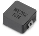
 | 74437324022 | SPEC | 9 files | Active i| Production is active. Expected lifetime: >10 years. | WE-LHMI SMT Power Inductor | 2.2 | 4.05 | 4.45 | 8.4 | 61 | 49 | SMT |
| Order Code | Datasheet | Simulation | |
|---|---|---|---|
 | 74437324022 | SPEC |
| Samples |
|---|
| Order Code | Datasheet | Simulation | Downloads | Status | Product series | L (µH) | IRP,40K (A) | ISAT,10% (A) | ISAT,30% (A) | RDC max. (mΩ) | fres (MHz) | Mount | Samples |
|---|


