IC manufacturers (107)
- All manufacturers
 Analog Devices
 Infineon Technologies
 Microchip
 Onsemi
 Renesas
 ROHM
ROHM STMicroelectronics
 Texas Instruments
- 3peak incorporated (35)
- Ablic (23)
- Acco Semiconductor (1)
- Advanced Power (4)
- Allegro Microsystems (100)
- Alpha & Omega Semiconductor (37)
- AnalogySemi (3)
- AnDAPT Inc (204)
- Anpec (13)
- AXElite (2)
- Backward (6)
- Bright Power Semiconductor (1)
- Broadcom (46)
- Cambridge GaN Devices (18)
- Chipanalog Micro (10)
- Cologne Chips (1)
- Convenient Power (1)
- Dialog Semiconductor (12)
- Diodes Incorporated (265)
- Divimath (8)
- Einnosemi (4)
- Elmos AG (1)
- EPC (146)
- e-Peas Semiconductors (1)
- Eta Solutions Co. Ltd. (9)
- GaN Systems (8)
- GaNPower (3)
- Giantec (1)
- Gosemicon (2)
- Gstek Wuxi (1)
- Helix Semiconductor (7)
- IKON (1)
- Indie Semiconductor (8)
- Innovision Semiconductor Inc (2)
- Intel (68)
- Inventchip Technology (3)
- ISSI (51)
- JoulWatt (20)
- KDPOF (3)
- Kinetic Technology (8)
- Lattice semiconductor Corporation (38)
- Littelfuse (1)
- Lumissil Microsystems (8)
- M3 Technology (M3Tek) (7)
- Macnica (22)
- Marvell Semiconductor (1)
- MaxLinear (181)
- Menlo Micro (1)
- MikroE (25)
- MindCet (2)
- Monolithic Power Systems (996)
- Navitas Semiconductor Inc (6)
- NewEdge Technologies, Inc. (1)
- Nexperia (268)
- Nisshinbo Micro Device Inc. (9)
- Nordic Semiconductor (1)
- Novosense Micro (1)
- NXP (346)
- O2 Micro International Ltd (10)
- On Bright (7)
- Panasonic (2)
- PN Junction Semiconductor (2)
- Power Integrations (117)
- Powermat (1)
- Pulsiv (19)
- Qorvo (99)
- Realsil SuRealsil(tek) Microelectronics (1)
- Richtek (297)
- Sanken Electric Co., Ltd. (16)
- Sckipio (6)
- Semtech (86)
- SG-Micro (62)
- SiFive (2)
- Silanna Semiconductor (9)
- Silergy Corporation (34)
- Silicon Laboratory Inc. (108)
- Silicontent Technology (59)
- Silvertel (59)
- Skycore Semiconductors (1)
- Skyworks (33)
- Southchip (29)
- Summit Wireless (1)
- Tagore Tech (7)
- Taiwan Semiconductor (1)
- TDK Corporation (1)
- Tempo Semiconductor (1)
- Torex (37)
- Toshiba (31)
- Transphorm (21)
- TransSIP (2)
- Union (21)
- uPI Semiconductor (2)
- Valens Semiconductor (31)
- VisIC (1)
- Wise Integration (3)
- Wolfspeed (23)
- Xilinx (22)
- XL Semiconductor (3)
- XYSemi (62)
Texas Instruments UCC27211DPRR | Demoboard TIDA-01606 Gate Driver
10-kW, bidirectional three-phase three-level (T-type) inverter and PFC reference design
Overview
| Topology | Half-Bridge Converter symmetrical isolated |
| Input voltage | 120 V |
| IC revision | F |
Description
The UCC27210 and UCC27211 drivers are based on the popular UCC27200 and UCC27201 MOSFET drivers, but offer several significant performance improvements. Peak output pull-up and pull-down current has been increased to 4-A source and 4-A sink, and pull-up and pull-down resistance have been reduced to 0.9 Ω, thereby allowing for driving large power MOSFETs with minimized switching losses during the transition through the Miller Plateau of the MOSFET. The input structure is now able to directly handle –10 VDC, which increases robustness and also allows direct interface to gate-drive transformers without using rectification diodes. The inputs are also independent of supply voltage and have a maximum rating of 20-V.The switching node (HS pin) of the UCC2721x can handle –18 V maximum which allows the high-side channel to be protected from inherent negative voltages caused parasitic inductance and stray capacitance. The UCC27210 (Pseudo-CMOS inputs) and UCC27211 (TTL inputs) have increased hysteresis allowing for interface to analog or digital PWM controllers with enhanced noise immunity.The low-side and high-side gate drivers are independently controlled and matched to 2 ns between the turnon and turnoff of each other.An on-chip 120-V rated bootstrap diode eliminates the external discrete diodes. Undervoltage lockout is provided for both the high-side and the low-side drivers providing symmetric turnon and turnoff behavior and forcing the outputs low if the drive voltage is below the specified threshold.Both devices are offered in 8-pin SOIC (D), PowerPAD SOIC-8 (DDA), 4-mm × 4-mm SON-8 (DRM) and SON-10 (DPR) packages.
Features
- Drives Two N-Channel MOSFETs in High-Side and Low-Side Configuration With Independent Inputs
- Maximum Boot Voltage 120-V DC
- 4-A Sink, 4-A Source Output Currents
- 0.9-Ω Pullup and Pulldown Resistance
- Input Pins Can Tolerate –10 V to 20 V and Are Independent of Supply Voltage Range
- TTL or Pseudo-CMOS Compatible Input Versions
- 8-V to 17-V VDD Operating Range, (20-V Absolute Maximum)
- 7.2-ns Rise and 5.5-ns Fall Time With 1000-pF Load
- Fast Propagation Delay Times (18 ns Typical)
- 2-ns Delay Matching
- Symmetrical Undervoltage Lockout for High-Side and Low-Side Driver
- All Industry Standard Packages Available (SOIC-8,PowerPAD™ SOIC-8, 4-mm × 4-mm SON-8 and 4-mm × 4-mm SON-10)
- Specified from –40 to 140 °C
Typical applications
- Half-Bridge and Full-Bridge Converters, Push-Pull Converters, High-Voltage Synchronous-Buck Converters, Two-Switch Forward Converters, Active-Clamp Forward Converters, Class-D Audio Amplifiers
- Power Supplies for Telecom, Datacom, and Merchant
More information
Products
Order Code | Datasheet | Simulation | Downloads | Status | Product series | λDom typ.(nm) | Emitting Color | λPeak typ.(nm) | IV typ.(mcd) | VF typ.(V) | Chip Technology | 2θ50% typ.(°) | C | Tol. C | VR(V (DC)) | Size | Operating Temperature | Q | DF(%) | RISO | Ceramic Type | L(mm) | W(mm) | H(mm) | Fl(mm) | Packaging | Pins | Type | Mount | IR(A) | Working Voltage(V (AC)) | SamplesAvailability & Sample | ||||||||||||||||||||||||||||||||||||||||||||||||||||||||||||||||||||||||||||||||||||||||||||||||||||||||||||||||||||||||||||||||||||||||||||||||||||||||||||||||||||||||||||||||||||||||||||||||||||||||||||||||||||||||||||||||||||||||||||||||||||||||||||||||||||||||||||||||||||||||||||||||||||||||||||||||||||||||||||||||||||||||||||||||||||||||||||||||||||||||||||||||||||||||||||||||||||||||||||||||||||||||||||||||||||||||||||||||||||||||||||||||||||||||||||||||||||||||||||||||||||||||||||||||||||||||||||||||||||||||||||||||||||||||||||||||||||||||||||||||||||||||||||||||||||||||||||||||||||||||||||||||||||||||||||||||||||||||||||||||||||||||||||||||||||||||||||||||||||||||||||||||||||||||||||||||||||||||||||||||||||||||||||||||||||||||||||||||||||||||||||||||||||||||||||||||||||||||||||||||||||||||||||||||||||||||||||||||||||||||||||||||||||||||||||||||||||||||||||||||||||||||||||||||||||||||||||||||||||||||||||||||||||||||||||||||||||||||||||||||||||||
|---|---|---|---|---|---|---|---|---|---|---|---|---|---|---|---|---|---|---|---|---|---|---|---|---|---|---|---|---|---|---|---|---|---|---|---|---|---|---|---|---|---|---|---|---|---|---|---|---|---|---|---|---|---|---|---|---|---|---|---|---|---|---|---|---|---|---|---|---|---|---|---|---|---|---|---|---|---|---|---|---|---|---|---|---|---|---|---|---|---|---|---|---|---|---|---|---|---|---|---|---|---|---|---|---|---|---|---|---|---|---|---|---|---|---|---|---|---|---|---|---|---|---|---|---|---|---|---|---|---|---|---|---|---|---|---|---|---|---|---|---|---|---|---|---|---|---|---|---|---|---|---|---|---|---|---|---|---|---|---|---|---|---|---|---|---|---|---|---|---|---|---|---|---|---|---|---|---|---|---|---|---|---|---|---|---|---|---|---|---|---|---|---|---|---|---|---|---|---|---|---|---|---|---|---|---|---|---|---|---|---|---|---|---|---|---|---|---|---|---|---|---|---|---|---|---|---|---|---|---|---|---|---|---|---|---|---|---|---|---|---|---|---|---|---|---|---|---|---|---|---|---|---|---|---|---|---|---|---|---|---|---|---|---|---|---|---|---|---|---|---|---|---|---|---|---|---|---|---|---|---|---|---|---|---|---|---|---|---|---|---|---|---|---|---|---|---|---|---|---|---|---|---|---|---|---|---|---|---|---|---|---|---|---|---|---|---|---|---|---|---|---|---|---|---|---|---|---|---|---|---|---|---|---|---|---|---|---|---|---|---|---|---|---|---|---|---|---|---|---|---|---|---|---|---|---|---|---|---|---|---|---|---|---|---|---|---|---|---|---|---|---|---|---|---|---|---|---|---|---|---|---|---|---|---|---|---|---|---|---|---|---|---|---|---|---|---|---|---|---|---|---|---|---|---|---|---|---|---|---|---|---|---|---|---|---|---|---|---|---|---|---|---|---|---|---|---|---|---|---|---|---|---|---|---|---|---|---|---|---|---|---|---|---|---|---|---|---|---|---|---|---|---|---|---|---|---|---|---|---|---|---|---|---|---|---|---|---|---|---|---|---|---|---|---|---|---|---|---|---|---|---|---|---|---|---|---|---|---|---|---|---|---|---|---|---|---|---|---|---|---|---|---|---|---|---|---|---|---|---|---|---|---|---|---|---|---|---|---|---|---|---|---|---|---|---|---|---|---|---|---|---|---|---|---|---|---|---|---|---|---|---|---|---|---|---|---|---|---|---|---|---|---|---|---|---|---|---|---|---|---|---|---|---|---|---|---|---|---|---|---|---|---|---|---|---|---|---|---|---|---|---|---|---|---|---|---|---|---|---|---|---|---|---|---|---|---|---|---|---|---|---|---|---|---|---|---|---|---|---|---|---|---|---|---|---|---|---|---|---|---|---|---|---|---|---|---|---|---|---|---|---|---|---|---|---|---|---|---|---|---|---|---|---|---|---|---|---|---|---|---|---|---|---|---|---|---|---|---|---|---|---|---|---|---|---|---|---|---|---|---|---|---|---|---|---|---|---|---|---|---|---|---|---|---|---|---|---|---|---|---|---|---|---|---|---|---|---|---|---|---|---|---|---|---|---|---|---|---|---|---|---|---|---|---|---|---|---|---|---|---|---|---|---|---|---|---|---|---|---|---|---|---|---|---|---|---|---|---|---|---|---|---|---|---|---|---|---|---|---|---|---|---|---|---|---|---|---|---|---|---|---|---|---|---|---|---|---|---|---|---|---|---|---|---|---|---|---|---|---|---|---|---|---|---|---|---|---|---|---|---|---|---|---|---|---|---|---|---|---|---|---|---|---|---|---|---|---|---|---|---|---|---|---|---|---|---|---|---|---|---|---|---|---|---|---|---|---|---|---|---|---|---|---|---|---|---|---|---|---|---|---|---|---|---|---|---|---|---|---|---|---|---|---|---|---|---|---|---|---|---|---|---|---|---|---|---|---|---|---|---|---|---|---|---|---|---|---|---|---|---|---|---|---|---|---|---|---|---|---|---|---|---|---|---|---|---|---|---|---|---|---|---|---|---|---|---|---|---|---|---|---|---|---|---|---|---|---|---|---|---|---|---|---|---|---|---|---|---|---|---|---|---|---|---|---|---|---|---|---|---|---|---|---|---|---|---|---|---|---|---|---|---|---|---|---|---|---|---|---|---|---|---|---|---|---|---|---|---|---|---|---|---|---|---|---|---|---|---|---|---|---|---|---|---|---|---|---|---|---|---|---|---|---|---|---|---|---|---|
| Log in now to view availability and request availability forecasts. LOGIN | ||||||||||||||||||||||||||||||||||||||||||||||||||||||||||||||||||||||||||||||||||||||||||||||||||||||||||||||||||||||||||||||||||||||||||||||||||||||||||||||||||||||||||||||||||||||||||||||||||||||||||||||||||||||||||||||||||||||||||||||||||||||||||||||||||||||||||||||||||||||||||||||||||||||||||||||||||||||||||||||||||||||||||||||||||||||||||||||||||||||||||||||||||||||||||||||||||||||||||||||||||||||||||||||||||||||||||||||||||||||||||||||||||||||||||||||||||||||||||||||||||||||||||||||||||||||||||||||||||||||||||||||||||||||||||||||||||||||||||||||||||||||||||||||||||||||||||||||||||||||||||||||||||||||||||||||||||||||||||||||||||||||||||||||||||||||||||||||||||||||||||||||||||||||||||||||||||||||||||||||||||||||||||||||||||||||||||||||||||||||||||||||||||||||||||||||||||||||||||||||||||||||||||||||||||||||||||||||||||||||||||||||||||||||||||||||||||||||||||||||||||||||||||||||||||||||||||||||||||||||||||||||||||||||||||||||||||||||||||||||||||||||||||||||||||||||||||||||||||||||
 | SPECWL-SMCW SMT Mono-color Chip LED Waterclear, 525 nm, Green | Availability – | Downloads27 files RAY files
| Status Activei| Production is active. Expected lifetime: >10 years. | Product seriesWL-SMCW SMT Mono-color Chip LED Waterclear | Dominant Wavelength [typ.]525 nm | Emitting ColorGreen | Peak Wavelength [typ.]515 nm | Luminous Intensity [typ.]430 mcd | Forward Voltage [typ.]3.2 V | Chip TechnologyInGaN | Viewing Angle Phi 0° [typ.]140 ° | – | – | – | Size0603 | Operating Temperature -40 °C up to +85 °C | – | – | – | – | Length1.6 mm | Width0.8 mm | Height0.7 mm | – | PackagingTape and Reel | – | – | MountSMT | – | – | –Check availability | ||||||||||||||||||||||||||||||||||||||||||||||||||||||||||||||||||||||||||||||||||||||||||||||||||||||||||||||||||||||||||||||||||||||||||||||||||||||||||||||||||||||||||||||||||||||||||||||||||||||||||||||||||||||||||||||||||||||||||||||||||||||||||||||||||||||||||||||||||||||||||||||||||||||||||||||||||||||||||||||||||||||||||||||||||||||||||||||||||||||||||||||||||||||||||||||||||||||||||||||||||||||||||||||||||||||||||||||||||||||||||||||||||||||||||||||||||||||||||||||||||||||||||||||||||||||||||||||||||||||||||||||||||||||||||||||||||||||||||||||||||||||||||||||||||||||||||||||||||||||||||||||||||||||||||||||||||||||||||||||||||||||||||||||||||||||||||||||||||||||||||||||||||||||||||||||||||||||||||||||||||||||||||||||||||||||||||||||||||||||||||||||||||||||||||||||||||||||||||||||||||||||||||||||||||||||||||||||||||||||||||||||||||||||||||||||||||||||||||||||||||||||||||||||||||||||||||||||||||||||||||||||||||||||||||||||||||||||||||||||||||||||
| SPECWL-SMCW SMT Mono-color Chip LED Waterclear, 625 nm, Red | Availability – | Downloads27 files RAY files
| Status Activei| Production is active. Expected lifetime: >10 years. | Product seriesWL-SMCW SMT Mono-color Chip LED Waterclear | Dominant Wavelength [typ.]625 nm | Emitting ColorRed | Peak Wavelength [typ.]630 nm | Luminous Intensity [typ.]250 mcd | Forward Voltage [typ.]2 V | Chip TechnologyAlInGaP | Viewing Angle Phi 0° [typ.]140 ° | – | – | – | Size0603 | Operating Temperature -40 °C up to +85 °C | – | – | – | – | Length1.6 mm | Width0.8 mm | Height0.7 mm | – | PackagingTape and Reel | – | – | MountSMT | – | – | –Check availability | ||||||||||||||||||||||||||||||||||||||||||||||||||||||||||||||||||||||||||||||||||||||||||||||||||||||||||||||||||||||||||||||||||||||||||||||||||||||||||||||||||||||||||||||||||||||||||||||||||||||||||||||||||||||||||||||||||||||||||||||||||||||||||||||||||||||||||||||||||||||||||||||||||||||||||||||||||||||||||||||||||||||||||||||||||||||||||||||||||||||||||||||||||||||||||||||||||||||||||||||||||||||||||||||||||||||||||||||||||||||||||||||||||||||||||||||||||||||||||||||||||||||||||||||||||||||||||||||||||||||||||||||||||||||||||||||||||||||||||||||||||||||||||||||||||||||||||||||||||||||||||||||||||||||||||||||||||||||||||||||||||||||||||||||||||||||||||||||||||||||||||||||||||||||||||||||||||||||||||||||||||||||||||||||||||||||||||||||||||||||||||||||||||||||||||||||||||||||||||||||||||||||||||||||||||||||||||||||||||||||||||||||||||||||||||||||||||||||||||||||||||||||||||||||||||||||||||||||||||||||||||||||||||||||||||||||||||||||||||||||||||||||
SPECWCAP-CSGP MLCCs 50 V(DC), –, – | Availability – | Status Activei| Production is active. Expected lifetime: >10 years. | Product seriesWCAP-CSGP MLCCs 50 V(DC) | – | – | – | – | – | – | – | Capacitance100 nF | Capacitance±10% | Rated Voltage50 V (DC) | Size0603 | Operating Temperature -55 °C up to +125 °C | – | Dissipation Factor3 % | Insulation Resistance5 GΩ | Ceramic TypeX7R Class II | Length1.6 mm | Width0.8 mm | Height0.8 mm | Pad Dimension0.4 mm | Packaging7" Tape & Reel | – | – | – | – | – | –Check availability | ||||||||||||||||||||||||||||||||||||||||||||||||||||||||||||||||||||||||||||||||||||||||||||||||||||||||||||||||||||||||||||||||||||||||||||||||||||||||||||||||||||||||||||||||||||||||||||||||||||||||||||||||||||||||||||||||||||||||||||||||||||||||||||||||||||||||||||||||||||||||||||||||||||||||||||||||||||||||||||||||||||||||||||||||||||||||||||||||||||||||||||||||||||||||||||||||||||||||||||||||||||||||||||||||||||||||||||||||||||||||||||||||||||||||||||||||||||||||||||||||||||||||||||||||||||||||||||||||||||||||||||||||||||||||||||||||||||||||||||||||||||||||||||||||||||||||||||||||||||||||||||||||||||||||||||||||||||||||||||||||||||||||||||||||||||||||||||||||||||||||||||||||||||||||||||||||||||||||||||||||||||||||||||||||||||||||||||||||||||||||||||||||||||||||||||||||||||||||||||||||||||||||||||||||||||||||||||||||||||||||||||||||||||||||||||||||||||||||||||||||||||||||||||||||||||||||||||||||||||||||||||||||||||||||||||||||||||||||||||||||||||||||
SPECWCAP-CSGP MLCCs 50 V(DC), –, – | Availability – | Status Activei| Production is active. Expected lifetime: >10 years. | Product seriesWCAP-CSGP MLCCs 50 V(DC) | – | – | – | – | – | – | – | Capacitance100 pF | Capacitance±5% | Rated Voltage50 V (DC) | Size0805 | Operating Temperature -55 °C up to +125 °C | Q-Factor1000 | – | Insulation Resistance10 GΩ | Ceramic TypeNP0 Class I | Length2 mm | Width1.25 mm | Height0.6 mm | Pad Dimension0.5 mm | Packaging7" Tape & Reel | – | – | – | – | – | –Check availability | ||||||||||||||||||||||||||||||||||||||||||||||||||||||||||||||||||||||||||||||||||||||||||||||||||||||||||||||||||||||||||||||||||||||||||||||||||||||||||||||||||||||||||||||||||||||||||||||||||||||||||||||||||||||||||||||||||||||||||||||||||||||||||||||||||||||||||||||||||||||||||||||||||||||||||||||||||||||||||||||||||||||||||||||||||||||||||||||||||||||||||||||||||||||||||||||||||||||||||||||||||||||||||||||||||||||||||||||||||||||||||||||||||||||||||||||||||||||||||||||||||||||||||||||||||||||||||||||||||||||||||||||||||||||||||||||||||||||||||||||||||||||||||||||||||||||||||||||||||||||||||||||||||||||||||||||||||||||||||||||||||||||||||||||||||||||||||||||||||||||||||||||||||||||||||||||||||||||||||||||||||||||||||||||||||||||||||||||||||||||||||||||||||||||||||||||||||||||||||||||||||||||||||||||||||||||||||||||||||||||||||||||||||||||||||||||||||||||||||||||||||||||||||||||||||||||||||||||||||||||||||||||||||||||||||||||||||||||||||||||||||||||||
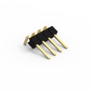 | SPECWR-PHD Pin Header - Single, –, – PCN pendingDue to a pending PCN, a modification of the component will be implemented soon. Please find the PCN below. If you have further questions please get in contact with our sales staff. | Simulation– | Availability – | Status Activei| Production is active. Expected lifetime: >10 years. | Product seriesWR-PHD Pin Header - Single | – | – | – | – | – | – | – | – | – | – | – | Operating Temperature -40 °C up to +105 °C | – | – | Insulation Resistance1000 MΩ | – | Length10.16 mm | – | – | – | PackagingBag | Pins4 | TypeAngled | MountTHT | Rated Current3 A | Working Voltage250 V (AC) | –Check availability | ||||||||||||||||||||||||||||||||||||||||||||||||||||||||||||||||||||||||||||||||||||||||||||||||||||||||||||||||||||||||||||||||||||||||||||||||||||||||||||||||||||||||||||||||||||||||||||||||||||||||||||||||||||||||||||||||||||||||||||||||||||||||||||||||||||||||||||||||||||||||||||||||||||||||||||||||||||||||||||||||||||||||||||||||||||||||||||||||||||||||||||||||||||||||||||||||||||||||||||||||||||||||||||||||||||||||||||||||||||||||||||||||||||||||||||||||||||||||||||||||||||||||||||||||||||||||||||||||||||||||||||||||||||||||||||||||||||||||||||||||||||||||||||||||||||||||||||||||||||||||||||||||||||||||||||||||||||||||||||||||||||||||||||||||||||||||||||||||||||||||||||||||||||||||||||||||||||||||||||||||||||||||||||||||||||||||||||||||||||||||||||||||||||||||||||||||||||||||||||||||||||||||||||||||||||||||||||||||||||||||||||||||||||||||||||||||||||||||||||||||||||||||||||||||||||||||||||||||||||||||||||||||||||||||||||||||||||||||||||||||||||||
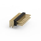 | SPECWR-PHD Pin Header - Dual, –, – PCN pendingDue to a pending PCN, a modification of the component will be implemented soon. Please find the PCN below. If you have further questions please get in contact with our sales staff. | Simulation– | Availability – | Status Activei| Production is active. Expected lifetime: >10 years. | Product seriesWR-PHD Pin Header - Dual | – | – | – | – | – | – | – | – | – | – | – | Operating Temperature -40 °C up to +105 °C | – | – | Insulation Resistance1000 MΩ | – | Length20.32 mm | – | – | – | PackagingBag | Pins16 | TypeAngled | MountTHT | Rated Current3 A | Working Voltage250 V (AC) | –Check availability | ||||||||||||||||||||||||||||||||||||||||||||||||||||||||||||||||||||||||||||||||||||||||||||||||||||||||||||||||||||||||||||||||||||||||||||||||||||||||||||||||||||||||||||||||||||||||||||||||||||||||||||||||||||||||||||||||||||||||||||||||||||||||||||||||||||||||||||||||||||||||||||||||||||||||||||||||||||||||||||||||||||||||||||||||||||||||||||||||||||||||||||||||||||||||||||||||||||||||||||||||||||||||||||||||||||||||||||||||||||||||||||||||||||||||||||||||||||||||||||||||||||||||||||||||||||||||||||||||||||||||||||||||||||||||||||||||||||||||||||||||||||||||||||||||||||||||||||||||||||||||||||||||||||||||||||||||||||||||||||||||||||||||||||||||||||||||||||||||||||||||||||||||||||||||||||||||||||||||||||||||||||||||||||||||||||||||||||||||||||||||||||||||||||||||||||||||||||||||||||||||||||||||||||||||||||||||||||||||||||||||||||||||||||||||||||||||||||||||||||||||||||||||||||||||||||||||||||||||||||||||||||||||||||||||||||||||||||||||||||||||||||||
 | 750343805 | SPECTransformer, –, – | Simulation– | Availability – | Status Activei| Production is active. Expected lifetime: >10 years. | Product series Transformer | – | – | – | – | – | – | – | – | – | – | SizeEPX7 | Operating Temperature -40 °C up to +125 °C | – | – | – | – | Length10.16 mm | Width9.14 mm | Height12.32 mm | – | PackagingTape and Reel | – | – | MountSMT | – | – | –Check availability | |||||||||||||||||||||||||||||||||||||||||||||||||||||||||||||||||||||||||||||||||||||||||||||||||||||||||||||||||||||||||||||||||||||||||||||||||||||||||||||||||||||||||||||||||||||||||||||||||||||||||||||||||||||||||||||||||||||||||||||||||||||||||||||||||||||||||||||||||||||||||||||||||||||||||||||||||||||||||||||||||||||||||||||||||||||||||||||||||||||||||||||||||||||||||||||||||||||||||||||||||||||||||||||||||||||||||||||||||||||||||||||||||||||||||||||||||||||||||||||||||||||||||||||||||||||||||||||||||||||||||||||||||||||||||||||||||||||||||||||||||||||||||||||||||||||||||||||||||||||||||||||||||||||||||||||||||||||||||||||||||||||||||||||||||||||||||||||||||||||||||||||||||||||||||||||||||||||||||||||||||||||||||||||||||||||||||||||||||||||||||||||||||||||||||||||||||||||||||||||||||||||||||||||||||||||||||||||||||||||||||||||||||||||||||||||||||||||||||||||||||||||||||||||||||||||||||||||||||||||||||||||||||||||||||||||||||||||||||||||||||||||
| 750343804 | SPECTransformer, –, – | Simulation– | Availability – | Status Activei| Production is active. Expected lifetime: >10 years. | Product series Transformer | – | – | – | – | – | – | – | – | – | – | SizeEPX7 | Operating Temperature -40 °C up to +125 °C | – | – | – | – | Length10.16 mm | Width9.14 mm | Height12.32 mm | – | PackagingTape and Reel | – | – | MountSMT | – | – | –Check availability | |||||||||||||||||||||||||||||||||||||||||||||||||||||||||||||||||||||||||||||||||||||||||||||||||||||||||||||||||||||||||||||||||||||||||||||||||||||||||||||||||||||||||||||||||||||||||||||||||||||||||||||||||||||||||||||||||||||||||||||||||||||||||||||||||||||||||||||||||||||||||||||||||||||||||||||||||||||||||||||||||||||||||||||||||||||||||||||||||||||||||||||||||||||||||||||||||||||||||||||||||||||||||||||||||||||||||||||||||||||||||||||||||||||||||||||||||||||||||||||||||||||||||||||||||||||||||||||||||||||||||||||||||||||||||||||||||||||||||||||||||||||||||||||||||||||||||||||||||||||||||||||||||||||||||||||||||||||||||||||||||||||||||||||||||||||||||||||||||||||||||||||||||||||||||||||||||||||||||||||||||||||||||||||||||||||||||||||||||||||||||||||||||||||||||||||||||||||||||||||||||||||||||||||||||||||||||||||||||||||||||||||||||||||||||||||||||||||||||||||||||||||||||||||||||||||||||||||||||||||||||||||||||||||||||||||||||||||||||||||||||||||
| Expected Availability | Opening inventory | Quantity |
|---|---|---|
| Current Availability | – | – |