IC manufacturers (104)
- All manufacturers
 Analog Devices
 Infineon Technologies
 Microchip
 Onsemi
 Renesas
 ROHM
ROHM STMicroelectronics
 Texas Instruments
- 3peak incorporated (28)
- Ablic (23)
- Acco Semiconductor (1)
- Advanced Power (4)
- Allegro Microsystems (97)
- Alpha & Omega Semiconductor (37)
- AnalogySemi (3)
- AnDAPT Inc (204)
- Anpec (13)
- AXElite (2)
- Backward (6)
- Bright Power Semiconductor (1)
- Broadcom (45)
- Cambridge GaN Devices (18)
- Chipanalog Micro (10)
- Cologne Chips (1)
- Convenient Power (1)
- Dialog Semiconductor (12)
- Diodes Incorporated (255)
- Divimath (8)
- Elmos AG (1)
- EPC (135)
- e-Peas Semiconductors (1)
- Eta Solutions Co. Ltd. (9)
- GaN Systems (8)
- GaNPower (3)
- Giantec (1)
- Gstek Wuxi (1)
- Helix Semiconductor (7)
- IKON (1)
- Indie Semiconductor (8)
- Innovision Semiconductor Inc (2)
- Intel (68)
- Inventchip Technology (3)
- ISSI (51)
- JoulWatt (20)
- KDPOF (3)
- Kinetic Technology (8)
- Lattice semiconductor Corporation (30)
- Littelfuse (1)
- Lumissil Microsystems (8)
- M3 Technology (M3Tek) (7)
- Macnica (22)
- Marvell Semiconductor (1)
- MaxLinear (181)
- Menlo Micro (1)
- MikroE (21)
- MindCet (2)
- Monolithic Power Systems (979)
- Navitas Semiconductor Inc (6)
- NewEdge Technologies, Inc. (1)
- Nexperia (263)
- Nisshinbo Micro Device Inc. (10)
- Nordic Semiconductor (1)
- Novosense Micro (1)
- NXP (327)
- O2 Micro International Ltd (10)
- On Bright (7)
- Panasonic (2)
- PN Junction Semiconductor (2)
- Power Integrations (120)
- Powermat (1)
- Pulsiv (19)
- Qorvo (95)
- Realsil SuRealsil(tek) Microelectronics (1)
- Richtek (297)
- Sanken Electric Co., Ltd. (16)
- Sckipio (6)
- Semtech (87)
- SG-Micro (49)
- SiFive (2)
- Silanna Semiconductor (9)
- Silergy Corporation (33)
- Silicon Laboratory Inc. (103)
- Silicontent Technology (59)
- Silvertel (61)
- Skycore Semiconductors (1)
- Skyworks (33)
- Southchip (8)
- Summit Wireless (1)
- Tagore Tech (7)
- Taiwan Semiconductor (1)
- TDK Corporation (1)
- Tempo Semiconductor (1)
- Torex (37)
- Toshiba (25)
- Transphorm (21)
- TransSIP (2)
- Union (21)
- uPI Semiconductor (2)
- Valens Semiconductor (30)
- Wise Integration (1)
- Wolfspeed (23)
- Xilinx (22)
- XL Semiconductor (3)
- XYSemi (62)
Overview
| Topology | Boost Converter |
| Input voltage | 5-36 V |
| Output 1 | 50 V / 0.33 A |
Description
Demonstration Circuit DC2013A is a 60V LED driver with internal 4A switch featuring the LT®3952 monolithic LED driver. It accepts an input voltage from 5V to 36V (with transient to 42V) and boosts to a single string of LEDs up to 50V LEDs at 330mA. DC2013A features an integrated 4A switch, constant-current and constant-voltage output control as well as input current limit and monitoring.The LT3952 has a wide input voltage range down to 3V and up to 42V. It has adjustable switching frequency between 200kHz and 3MHz. It has an option for external frequency synchronization or spread spectrum frequencymodulation. It has high PWM dimming capability from an external signal and can be PWM dimmed with an internally generated PWM oscillator and analog input signal. It can be analog dimmed with a control voltage on its control pin. LT3952 features both Open-LED and Short-LED (LED+to GND) protection as well as fault output flags for each. Although DC2013A is assembled as a boost LED driver, it can be altered to be run as a buck mode, buck-boost mode or boost-buck LED driver.There is another demonstration circuit featuring LT3952 at 2.0MHz (DC2361A).DC2013A features an option to turn on spread spectrum by simply changing the position of a jumper from NO SPREAD to SPREAD or to EXTERNAL SYNC.Small ceramic input and output capacitors are used to save space and cost. The Open-LED overvoltage protection uses the IC’s constant-voltage regulation loop to regulate the output to approximately 55V if the LED string is opened There is undervoltage and overvoltage lockout that can beadjusted on the circuit with a few simple resistor choices.There is an EMI filter on the input of DC2013A. This EMIfilter has both an LC stage to reduce EMI below 20MHz and a ferrite bead to reduce higher frequency EMI. The PCB layout contains a small hot-loop for minimized highfrequency EMI. The EMI filter can be used by connecting to the “EMI VIN” terminal. However, if the EMI filter is not needed, the input connection can be directly to the PVIN terminal. If the EMI filter is not used, it is recommended to remove the EMI filter if EMI measurements are beingmade from the PVIN terminal for base EMI testing. It can be replaced for EMI testing at the EMI VIN terminalThe LT3952 data sheet gives a complete description of the part, operation and applications information. The data sheet must be read in conjunction with this Demo Manual for Demonstration Circuit 2013A. The LT3952EFE is assembled in a 28-lead plastic TSSOP (FE) package with a thermally enhanced ground pad. Proper board layout is essential for maximum thermal performance. See the data sheet section “Layout Considerations”.
Features
Remarks
- IN Optional circuit 4.7uH inductor is used.
More information
Products
| Order Code | Datasheet | Simulation | Downloads | Status | Product series | L (µH) | ISAT (A) | RDC max. (mΩ) | fres (MHz) | Mount | Pins (pcs) | Pitch (mm) | Rows | H (mm) | Gender | Type | IR (A) | Packaging | Samples | |
|---|---|---|---|---|---|---|---|---|---|---|---|---|---|---|---|---|---|---|---|---|
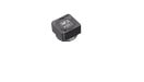 | 7447798151 | SPEC | 9 files | Active i| Production is active. Expected lifetime: >10 years. | WE-PDF SMT Power Inductor | 15 | 4 | 25.8 | 19 | SMT | 2 | – | – | 6.1 | – | – | 5.45 | – | ||
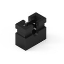 | 60800213421 | SPEC | – | 3 files | Active i| Production is active. Expected lifetime: >10 years. | WR-PHD Jumper | – | – | – | – | – | 2 | 2 | – | – | Jumper | – | 3 | Bag | |
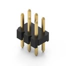 | 62000621121 | SPEC | – | 7 files | Active i| Production is active. Expected lifetime: >10 years. | WR-PHD Pin Header | – | – | – | – | THT | 6 | 2 | Dual | – | Pin Header | Straight | 2 | Bag |
| Order Code | Datasheet | Simulation | |
|---|---|---|---|
| 7447798151 | SPEC | |
| 60800213421 | SPEC | – |
| 62000621121 | SPEC | – |
| Samples |
|---|
| Order Code | Datasheet | Simulation | Downloads | Status | Product series | L (µH) | ISAT (A) | RDC max. (mΩ) | fres (MHz) | Mount | Pins (pcs) | Pitch (mm) | Rows | H (mm) | Gender | Type | IR (A) | Packaging | Samples |
|---|
