IC manufacturers (104)
- All manufacturers
 Analog Devices
 Infineon Technologies
 Microchip
 Onsemi
 Renesas
 ROHM
ROHM STMicroelectronics
 Texas Instruments
- 3peak incorporated (28)
- Ablic (23)
- Acco Semiconductor (1)
- Advanced Power (4)
- Allegro Microsystems (97)
- Alpha & Omega Semiconductor (37)
- AnalogySemi (3)
- AnDAPT Inc (204)
- Anpec (13)
- AXElite (2)
- Backward (6)
- Bright Power Semiconductor (1)
- Broadcom (45)
- Cambridge GaN Devices (18)
- Chipanalog Micro (10)
- Cologne Chips (1)
- Convenient Power (1)
- Dialog Semiconductor (12)
- Diodes Incorporated (255)
- Divimath (8)
- Elmos AG (1)
- EPC (135)
- e-Peas Semiconductors (1)
- Eta Solutions Co. Ltd. (9)
- GaN Systems (8)
- GaNPower (3)
- Giantec (1)
- Gstek Wuxi (1)
- Helix Semiconductor (7)
- IKON (1)
- Indie Semiconductor (8)
- Innovision Semiconductor Inc (2)
- Intel (68)
- Inventchip Technology (3)
- ISSI (51)
- JoulWatt (20)
- KDPOF (3)
- Kinetic Technology (8)
- Lattice semiconductor Corporation (30)
- Littelfuse (1)
- Lumissil Microsystems (8)
- M3 Technology (M3Tek) (7)
- Macnica (22)
- Marvell Semiconductor (1)
- MaxLinear (181)
- Menlo Micro (1)
- MikroE (21)
- MindCet (2)
- Monolithic Power Systems (979)
- Navitas Semiconductor Inc (6)
- NewEdge Technologies, Inc. (1)
- Nexperia (263)
- Nisshinbo Micro Device Inc. (10)
- Nordic Semiconductor (1)
- Novosense Micro (1)
- NXP (327)
- O2 Micro International Ltd (10)
- On Bright (7)
- Panasonic (2)
- PN Junction Semiconductor (2)
- Power Integrations (120)
- Powermat (1)
- Pulsiv (19)
- Qorvo (95)
- Realsil SuRealsil(tek) Microelectronics (1)
- Richtek (297)
- Sanken Electric Co., Ltd. (16)
- Sckipio (6)
- Semtech (87)
- SG-Micro (49)
- SiFive (2)
- Silanna Semiconductor (9)
- Silergy Corporation (33)
- Silicon Laboratory Inc. (103)
- Silicontent Technology (59)
- Silvertel (61)
- Skycore Semiconductors (1)
- Skyworks (33)
- Southchip (8)
- Summit Wireless (1)
- Tagore Tech (7)
- Taiwan Semiconductor (1)
- TDK Corporation (1)
- Tempo Semiconductor (1)
- Torex (37)
- Toshiba (25)
- Transphorm (21)
- TransSIP (2)
- Union (21)
- uPI Semiconductor (2)
- Valens Semiconductor (30)
- Wise Integration (1)
- Wolfspeed (23)
- Xilinx (22)
- XL Semiconductor (3)
- XYSemi (62)
Overview
| Topology | Buck-Boost Converter |
| Input voltage | 4-60 V |
| Switching frequency | 600-2000 kHz |
| Output 1 | 12 V / 4 A |
| IC revision | A |
Description
Demonstration circuit 2598A is a 60V 2MHz synchronousbuck-boost controller featuring the LT®8390A. It acceptsan input voltage from 4V to 24V (with transient to 60V) andregulates 12V output at up to 4A. DC2598A features highefficiency and 2MHz switching frequency, a high speedfor a 4-switch buck-boost controller. It has a PGOOD flag,short-circuit fault protection, ISMON current-monitoringoutput signal, and spread spectrum frequency modulation(SSFM) or frequency synchronization.The LT8390A has a wide input voltage range from 4V to60V. It can regulate an output as a boost, a buck, or a4-switch boost-buck controller. It has adjustable switchingfrequency between 600kHz and 2MHz. It has an optionfor external frequency synchronization or spread spectrumfrequency modulation. Its high switching frequencyis unique to buck-boost controller ICs. Because of this, itcan be used for high power when the input may be above,below, or equal to the output.DC2598A features an option to turn on spread spectrumby simply changing the position of a jumper from “NOSSFM/SYNC” to “SSFM” (or to ”SYNC”).Small ceramic input and output capacitors are used tosave space and cost. There is a protection diode fromLED+ to GND to prevent negative ringing during a shortcircuitwith long wires. Optional EMI input, output, andgate resistor component placeholders exist when a lowEMI application is needed.Under voltage lockout can be adjusted with a few resistorsand output voltage can be changed from 12V with FB resistorschanges. Please note that higher voltage outputs mayrequire higher voltage MOSFETs and output capacitors.The LT8390A data sheet gives a complete description of thepart, operation and applications information. The data sheetmust be read in conjunction with this demo manual fordemonstration circuit 2598A. The LT8390AEUFD is assembledin a 28-lead 4mm × 5mm plastic QFN package with athermally enhanced ground pad. LT8390A is also availablein a 28-Lead plastic TSSOP (FE) package. Proper boardlayout is essential for maximum thermal performance. Seethe data sheet section “Layout Considerations”.
More information
Products
| Order Code | Datasheet | Simulation | Downloads | Status | Product series | L (mm) | f (mm) | L (µH) | IRP,40K (A) | ISAT,10% (A) | ISAT,30% (A) | RDC max. (mΩ) | fres (MHz) | Mount | Pins (pcs) | Pitch (mm) | Rows | H (mm) | Gender | Type | IR (A) | Packaging | Samples | |
|---|---|---|---|---|---|---|---|---|---|---|---|---|---|---|---|---|---|---|---|---|---|---|---|---|
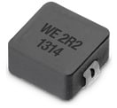 | 74437336010 | SPEC | 9 files | Active i| Production is active. Expected lifetime: >10 years. | WE-LHMI SMT Power Inductor | 5.7 | – | 1 | 8.6 | 7.4 | 14.2 | 14 | 60 | SMT | 2 | – | – | 2.8 | – | – | – | – | ||
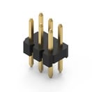 | 62000621121 | SPEC | – | 7 files | Active i| Production is active. Expected lifetime: >10 years. | WR-PHD Pin Header | 6 | – | – | – | – | – | – | – | THT | 6 | 2 | Dual | – | Pin Header | Straight | 2 | Bag | |
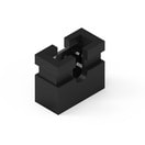
 | 702933000 | SPEC | – | 3 files | Active i| Production is active. Expected lifetime: >10 years. | WA-SNSR Self-Retaining Spacer | 9.5 | 4.8 | – | – | – | – | – | – | – | – | – | – | – | – | – | – | – | |
 | 60800213421 | SPEC | – | 3 files | Active i| Production is active. Expected lifetime: >10 years. | WR-PHD Jumper | – | – | – | – | – | – | – | – | – | 2 | 2 | – | – | Jumper | – | 3 | Bag |
| Order Code | Datasheet | Simulation | |
|---|---|---|---|
| 74437336010 | SPEC | |
| 62000621121 | SPEC | – |
| 702933000 | SPEC | – |
| 60800213421 | SPEC | – |
| Samples |
|---|
| Order Code | Datasheet | Simulation | Downloads | Status | Product series | L (mm) | f (mm) | L (µH) | IRP,40K (A) | ISAT,10% (A) | ISAT,30% (A) | RDC max. (mΩ) | fres (MHz) | Mount | Pins (pcs) | Pitch (mm) | Rows | H (mm) | Gender | Type | IR (A) | Packaging | Samples |
|---|
