IC manufacturers (104)
- All manufacturers
 Analog Devices
 Infineon Technologies
 Microchip
 Onsemi
 Renesas
 ROHM
ROHM STMicroelectronics
 Texas Instruments
- 3peak incorporated (28)
- Ablic (23)
- Acco Semiconductor (1)
- Advanced Power (4)
- Allegro Microsystems (97)
- Alpha & Omega Semiconductor (37)
- AnalogySemi (3)
- AnDAPT Inc (204)
- Anpec (13)
- AXElite (2)
- Backward (6)
- Bright Power Semiconductor (1)
- Broadcom (45)
- Cambridge GaN Devices (18)
- Chipanalog Micro (10)
- Cologne Chips (1)
- Convenient Power (1)
- Dialog Semiconductor (12)
- Diodes Incorporated (255)
- Divimath (8)
- Elmos AG (1)
- EPC (135)
- e-Peas Semiconductors (1)
- Eta Solutions Co. Ltd. (9)
- GaN Systems (8)
- GaNPower (3)
- Giantec (1)
- Gstek Wuxi (1)
- Helix Semiconductor (7)
- IKON (1)
- Indie Semiconductor (8)
- Innovision Semiconductor Inc (2)
- Intel (68)
- Inventchip Technology (3)
- ISSI (51)
- JoulWatt (20)
- KDPOF (3)
- Kinetic Technology (8)
- Lattice semiconductor Corporation (30)
- Littelfuse (1)
- Lumissil Microsystems (8)
- M3 Technology (M3Tek) (7)
- Macnica (22)
- Marvell Semiconductor (1)
- MaxLinear (181)
- Menlo Micro (1)
- MikroE (21)
- MindCet (2)
- Monolithic Power Systems (979)
- Navitas Semiconductor Inc (6)
- NewEdge Technologies, Inc. (1)
- Nexperia (263)
- Nisshinbo Micro Device Inc. (10)
- Nordic Semiconductor (1)
- Novosense Micro (1)
- NXP (327)
- O2 Micro International Ltd (10)
- On Bright (7)
- Panasonic (2)
- PN Junction Semiconductor (2)
- Power Integrations (120)
- Powermat (1)
- Pulsiv (19)
- Qorvo (95)
- Realsil SuRealsil(tek) Microelectronics (1)
- Richtek (297)
- Sanken Electric Co., Ltd. (16)
- Sckipio (6)
- Semtech (87)
- SG-Micro (49)
- SiFive (2)
- Silanna Semiconductor (9)
- Silergy Corporation (33)
- Silicon Laboratory Inc. (103)
- Silicontent Technology (59)
- Silvertel (61)
- Skycore Semiconductors (1)
- Skyworks (33)
- Southchip (8)
- Summit Wireless (1)
- Tagore Tech (7)
- Taiwan Semiconductor (1)
- TDK Corporation (1)
- Tempo Semiconductor (1)
- Torex (37)
- Toshiba (25)
- Transphorm (21)
- TransSIP (2)
- Union (21)
- uPI Semiconductor (2)
- Valens Semiconductor (30)
- Wise Integration (1)
- Wolfspeed (23)
- Xilinx (22)
- XL Semiconductor (3)
- XYSemi (62)
Analog Devices LTC3644 | Demoboard DC2383A-A
LTC3644 | Quad 17V, 1.25A Synchronous Step-Down Regulator with Ultralow Quiescent Current
Overview
| Topology | Buck Converter |
| Input voltage | 2.7-17 V |
| Output 1 | 2.5 V / 1.25 A |
| Output 2 | 1.8 V / 1.25 A |
| Output 3 | 3.3 V / 1.25 A |
| Output 4 | 1.2 V / 1.25 A |
Description
Demonstration circuit 2383A-A features the LTC3644: the wide input and output voltage range, high efficiency and power density, quad 1.25A outputs DC/DC synchronous step-down monolithic regulator. The input voltage range of DC2383A-A is 2.7V to 17V. The default demo board setting of VOUT1, VOUT2, VOUT3, VOUT4 is 1.2V, 3.3V, 2.5V and 1.8V at 1.25A maximum DC output current per channel. There are two assembly versions. The DC2383A-A features LTC3644 which operates at an internally fixed frequency of 1MHz (Typ), while the DC2383A-B features LTC3644-2 which operates at an internally fixed frequency of 2.25MHz (Typ). Peak current limit is internally fixed at 2.2A typical per channel. Each channel comes with independent run pin control and power good indicators. Phase shift selection of either 0 degree or 180 degrees between switch rising edge of channels 1, 2 and channels 3, 4 is also available.DC2383A-A provides optional onboard 0Ω jumpers to configure the LTC3644 as 4-phase dual 2.5A/2.5A outputs or 4-phase triple 2.5A/1.25A/1.25A outputs. Optional 0Ω jumpers connecting VIN1 to VIN2, VIN3, VIN4 are available for users to operate selected channels of LTC3644 at different input voltages than VIN1.A user-selectable MODE/SYNC input is provided to allow users to trade off ripple noise for light load efficiency: pulse-skipping mode (PS) or Burst Mode® operation delivers higher efficiency at light load while forced continuous conduction mode (FCM) is preferred for noise sensitive applications. The MODE/SYNC pin can also be used to synchronize the switching frequency to an external clock or set the phase shift between channels 1, 2 and channels 3, 4. Constant frequency, peak current mode control architecture and integrated internal control loop compensation network, allows very fast transient response to line and load changes while maintaining loop stability.
Features
- Quad Step-down Outputs: 1.25A per Channel
- Wide VIN Range: 2.7V to 17V
- Wide VOUT Range: 0.6V to VIN
- 1.25A/2.5A/3.75A/5A IOUT Configurable with One Inductor
- Integrated 300mΩ P-Channel/80mΩ N-Channel MOSFETs Provide Up to 93% Efficiency
- No-Load Burst Mode Operation IQ < 10µA with All Channels Enabled
- Constant Frequency (1MHz/2.25MHz) with ±50% Frequency Synchronization Range
- ±1% Output Voltage Accuracy
- Current Mode Operation for Excellent Line and Load Transient Response
- Full Dropout Operation (100% Duty Cycle)
- Phase Shift Programmable with External Clock
- 5mm × 5mm × 1.72mm BGA Package
Typical applications
- Battery Powered Systems
- Point-of-Load Supplies
- Portable – Handheld Scanners and Cameras
More information
Products
| Order Code | Datasheet | Downloads | Status | Product series | L (mm) | f (mm) | Pins (pcs) | Pitch (mm) | Rows | Gender | Type | IR (A) | Packaging | Samples | |
|---|---|---|---|---|---|---|---|---|---|---|---|---|---|---|---|
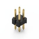 | 62000421121 | SPEC | 7 files | Active i| Production is active. Expected lifetime: >10 years. | WR-PHD Pin Header | 4 | – | 4 | 2 | Dual | Pin Header | Straight | 2 | Bag | |
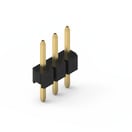 | 62000311121 | SPEC | 7 files | Active i| Production is active. Expected lifetime: >10 years. | WR-PHD Pin Header | 6 | – | 3 | 2 | Single | Pin Header | Straight | 2 | Bag | |
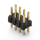 | 62000821121 | SPEC | 7 files | Active i| Production is active. Expected lifetime: >10 years. | WR-PHD Pin Header | 8 | – | 8 | 2 | Dual | Pin Header | Straight | 2 | Bag | |
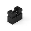
 | 702935000 | SPEC | 3 files | Active i| Production is active. Expected lifetime: >10 years. | WA-SNSR Self-Retaining Spacer | 12.7 | 4.8 | – | – | – | – | – | – | – | |
 | 60800213421 | SPEC | 3 files | Active i| Production is active. Expected lifetime: >10 years. | WR-PHD Jumper | – | – | 2 | 2 | – | Jumper | – | 3 | Bag |
| Order Code | Datasheet | |
|---|---|---|
| 62000421121 | SPEC |
| 62000311121 | SPEC |
| 62000821121 | SPEC |
| 702935000 | SPEC |
| 60800213421 | SPEC |
| Samples |
|---|
| Order Code | Datasheet | Downloads | Status | Product series | L (mm) | f (mm) | Pins (pcs) | Pitch (mm) | Rows | Gender | Type | IR (A) | Packaging | Samples |
|---|
