Analog Devices LTC3838EFE | Demoboard DC1626A-B
DC1626A-B - LTC3838EFE Demo Board (RSENSE) |4.5V ≤ VIN ≤ 26V; VOUT1 = 1.2V @ 15A, VOUT2 = 1.5V @ 15A
Overview
| Topology | Buck Converter |
| Input voltage | 4.5-26 V |
| Output 1 | 1.5 V / 15 A |
| Output 2 | 1.2 V / 15 A |
| IC revision | 2 |
Description
Demonstration circuit 1626A is a dual output 1.5V/15A and 1.2V/15A synchronous buck converter operating with a switching frequency of 300kHz over an input voltage range of 4.5V to 26V. The demo board comes in two versions. The -A version uses inductor DCR current sensingwith an iron powder inductor for high efficiency. The -B version uses a 2.5mΩ sense resistor for accurate current sensing with a low DCR ferrite inductor. The fixed on-time valley current mode architecture of the LTC3838 allows for a fast load step response (see Figures 6 to 9). The loadstep response can be tested with the on-board load step circuit and a bench pulse generator.
The demo board uses a high density, two sided drop-in layout. The entire converter, excluding the bulk output and input capacitors, fits within a compact 1.5" × 1.0" area on the board. The package style for the LTC3838EFE is a 38-lead TSSOP with an exposed ground pad.
Features
- MODE jumper to program either DCM or FCM at light or no load
- EXTVCC pin
- PLLIN pin to synchronize the converter to an external clock
- Remote sensing for VOUT1
- Optional resistors to tie the two phases together
- Each rail has its own RUN pin, PGOOD pin and TRACK/SS pin
More information
Products
| Order Code | Datasheet | Simulation | Downloads | Status | Product series | L (µH) | IRP,40K (A) | ISAT,10% (A) | ISAT,30% (A) | RDC max. (mΩ) | Material | LR (µH) | fres (MHz) | Samples | |
|---|---|---|---|---|---|---|---|---|---|---|---|---|---|---|---|
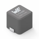
 | 7443330068 | SPEC | 9 files | Active i| Production is active. Expected lifetime: >10 years. | WE-HCC SMT High Current Cube Inductor | 0.68 | 27.2 | 41.4 | 46 | 2.65 | Ferrite | 0.67 | 140 |
| Order Code | Datasheet | Simulation | |
|---|---|---|---|
 | 7443330068 | SPEC |
| Samples |
|---|
| Order Code | Datasheet | Simulation | Downloads | Status | Product series | L (µH) | IRP,40K (A) | ISAT,10% (A) | ISAT,30% (A) | RDC max. (mΩ) | Material | LR (µH) | fres (MHz) | Samples |
|---|


