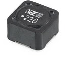
Anpec APW7437 | Demoboard Typical_Application_Circuit_2
18V Input, Dual 6A and 3A Synchronous Buck with Sync Pin
Overview
| Topology | Buck Converter |
| Input voltage | 4.5-18 V |
| Output 1 | 6 A |
| Output 2 | 3 A |
| IC revision | A.10 |
Description
The APW7437 is a two-channel synchronous mode PWM converter with 6A continuous current capability for one channel and 3A continuous current capability for the other one. Each channel of the APW7437 has independent enable and soft-start control pins, and It also allows the two regulators to start together by using the same enable signal and the same soft-start capacitor. In addition to changing the switching frequency through the I2C function, the APW7437 can also synchronize the switching frequency with an external clock frequency through the SYNC pin. The APW7437 also provides a 180-degree phase shifting technique to minimize switching noise. The output voltage of each channel can be adjusted using an external resistor divider or by adjusting the internal reference voltage through I2C. Other features include UVP, current limit , and OTP. The APW7437 is available in a TQFN5x5-28 package with small size and excellent thermal capacity
Features
- Wide Input Voltage from 4.5V to 18V.
- 6A/3A Output Current on Channel 1/2.
- Low IQ=150uA (typ.) per channel supply to improve Light Load Efficiency at Sync off. -Typical 0.6V +1%Internal Reference Voltage.
- Easy to use I2C interface
- Programmable VOUT by control VFB Reference Voltage from 408~790.5mV in 1.5mV steps.
- Adjustable Frequency in 4 steps, 500kHz, 600kHz, 800kHz and 1.2MHz
- Adjustable Voltage Step Slew Rate in 3 steps,
- 0.75mV/uSec, 1.5mV/uSec, 3mV/uSec
- Selectable PSM/PWM mode or PWM mode only
- Support 8 sets of Slave address by an resistor.
- Independent salve address for each channel.
- I2C Control Function: Soft-Enable and Soft Reset.
- Sync Pin Allows Synchronization to an External Clock from 500kHz to 2MHz. -Optimized Upper and Lower MOSFETs RDS_on for max Efficiency:
- N-CH MOSFET (28 mW) for CH1 High Side.
- N-CH MOSFET (16 mW) for CH1 Low Side.
- N-CH MOSFET (70 mW) for CH2 High Side.
- N-CH MOSFET (25 mW) for CH2 Low Side.
- Independent External Soft-Start Control for each channel.
- Separate EN and for Easy Sequencing. -PG pin indicating both Channels Power Good.
- Built in OVP, UVP, Current Limit and OTP.
- Low Cost TQFN5x5-28 package.
- Lead Free and Green Devices Available (RoHS Compliant)
Typical applications
- Digital Subscriber Line, Passive Optical Network, G.fast, Set-Top-Box
More information
Products
| Order Code | Datasheet | Simulation | Downloads | Status | Product series | L (µH) | IRP,40K (A) | ISAT (A) | RDC max. (mΩ) | fres (MHz) | Size | Version | Samples | |
|---|---|---|---|---|---|---|---|---|---|---|---|---|---|---|
 | 744771001 | SPEC | 9 files | Active i| Production is active. Expected lifetime: >10 years. | WE-PD SMT Power Inductor | 1.5 | 17.5 | 13.5 | 6 | 60 | 1260 | Standard |
| Samples |
|---|
| Order Code | Datasheet | Simulation | Downloads | Status | Product series | L (µH) | IRP,40K (A) | ISAT (A) | RDC max. (mΩ) | fres (MHz) | Size | Version | Samples |
|---|


