Overview
| Topology | SEPIC Buck-Boost Topology |
| Input voltage | 3-4.2 V |
| Output 1 | 3.3 V / 1 A |
| IC revision | A |
Description
The AT73C224-x is a family of ultra low cost Power Management Unit, available in asmall outline QFN 5x5mm package.The AT73C224-x family is optimized for portable applications, typically powered by aLi-Ion battery. The AT73C224-x device is also suitable to operate from a standard3.3V to 5.25V voltage rail. It includes four power supplies and a very low power RealtimeClock (RTC). In normal mode (main battery present), the backup battery isrecharged through a 2.6V RTC LDO.The AT73C224-x series offer different automatic start-up sequences (with varyingorders of power-on and specific default output values) and different soft managementmodes: dynamic (via SPI or TWI) with register access or static, with access to poweron/off of the four power supplies.Each AT73C224-x device is equipped with a very low power bandgap reference, lowpower 32 kHz and 1 MHz oscillators and an internal LDO used to generate the internalsupply (VINT) equal to 2.8V. Auxiliary cells, such as a power-on reset (POR) and avoltage monitor are used to control the system power-on (battery plugged in) andpower-off (battery unplugged).The four power supplies are named: BOOST1, BUCK2, LDO3 and LDO4.Table 1-1 lists the different devices available in the AT73C224-x series.
Features
- DC/DC Step-up Converter (BOOST) 3.3V to 5.2V, 1A, up to 90% Efficiency. Can be Usedas BUCK/BOOST in SEPIC Configuration
- DC/DC Step-down (BUCK) Synchronous Converter 0.9V to 3.4V, 500mA, up to 90%Efficiency, Pulse Skipping Capabilities for High Efficiency at Light Load Currents
- Two Low-Drop-Out Regulators 1.3V, 1.5V to 1.8V, 2.5V to 2.8V (100 mV Step), 3.3V,200 mA Maximum Load
- Ultra-low Power Real-time Clock (RTC) and Backup Battery Management– 2.6V RTC LDO for Backup Battery Charging– 32 kHz Crystal RTC Oscillator (1 μA)– RTC Circuit for Time and Date Information
- Activation of the Power Management Modules via Dedicated Enable Pin
- Automatic Start-up Sequences, POK Signal Indicating When Start-up is Completed
- Activation and Control of the Power Management Modules in Dynamic Mode (via SPI orTWI) or in Static Mode (On/Off of the Four Power Supplies)
- ITB Signal Indicating Short-circuits in DC/DC Converters
- Very Low Quiescent Current
- Minimum External Components Count
- Supply: from 2.8V to 5.25V (typ: Li-Ion Battery 3V to 4.2V)
- Available in a 32-pin 5x5 QFN Package
Typical applications
- Portable Music Players
- Multimedia Devices
- WLAN Portable Devices
More information
Products
| Order Code | Datasheet | Simulation | Downloads | Status | Product series | L (µH) | IR (A) | IRP,40K (A) | ISAT (A) | ISAT,10% (A) | ISAT,30% (A) | RDC max. (Ω) | fres (MHz) | Samples | |
|---|---|---|---|---|---|---|---|---|---|---|---|---|---|---|---|
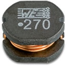
 | 744773022 | SPEC | 9 files | Active i| Production is active. Expected lifetime: >10 years. | WE-PD2 SMT Power Inductor | 2.2 | 2.5 | 3.5 | 3.38 | 4.1 | 4.7 | 0.071 | 85 | ||
 | 744773068 | SPEC | 9 files | Active i| Production is active. Expected lifetime: >10 years. | WE-PD2 SMT Power Inductor | 6.8 | 1.54 | 2.3 | 2.1 | 2.1 | 2.4 | 0.131 | 41 |
| Samples |
|---|
| Order Code | Datasheet | Simulation | Downloads | Status | Product series | L (µH) | IR (A) | IRP,40K (A) | ISAT (A) | ISAT,10% (A) | ISAT,30% (A) | RDC max. (Ω) | fres (MHz) | Samples |
|---|


