Overview
| Topology | Buck Converter |
| Input voltage | 85-270 V |
| Output 1 | 12 V / 0.25 A |
Description
This design note describes a very simple, low power, constant voltage output buck power converter intended for powering electronics for white goods, electrical meters, and industrial equipment where isolation from the AC mains is not required. The switching element in the converter is ON Semiconductor’s NCP107x series of monolithic switchers. In this reference design, the NCP1071 is utilized with a 100 kHz switching frequency and a maximum output current of 250 mA.This buck circuit design utilizes a simple charge pump or “bootstrap” type of voltage sensing and regulation scheme composed of D4, C5, Z1, Q1 and the associated passive components. This simple sensing technique eliminates the use of an optocoupler in the feedback loop. Z1 sets the approximate output voltage and Q1 acts as a simple error amplifier. Although the regulation is inferior to that of a conventional TL431 and optocoupler feedback circuit, it is typically adequate for most applications with a regulation of +/- 5% over loads from 100% down to about 1% max rated load. Below 1% the output will rise to the value of the overvoltage clamping zener Z2 across the output. For a 12 volt output, a typical value for this zener will be 15 volts and at no load, the output will be clamped at this level.The sensed voltage produced on C5 is also used to power the NCP1071 controller through D2 and limiting resistor R1 once the converter has started. This auxiliary Vcc to run the chip improves the overall efficiency of the circuit and prevents the controller from running in DSS mode under normal load conditions.Because of the low power output, a simple half-wave input rectifier/filter circuit is used comprised of D1 and C2. C1 and L1 form a conducted EMI filter that easily meets CE and UL level B requirements. C2 can be reduced to ½ the specified capacitance if a full-wave bridge rectifier circuit is used on the input.The 1.5 mH buck output inductor is available in several surface mount configurations from multiple vendors.
Features
Remarks:L1=1mHL2=1.5mH
Products
| Order Code | Datasheet | Simulation | Downloads | Status | Product series | L (µH) | IR (A) | ISAT,10% (A) | RDC max. (Ω) | fres (MHz) | Version | ISAT (A) | Samples | |
|---|---|---|---|---|---|---|---|---|---|---|---|---|---|---|
 | 744732102 | SPEC | 9 files | Active i| Production is active. Expected lifetime: >10 years. | WE-TI Radial Leaded Wire Wound Inductor | 1000 | 0.33 | 0.6 | 3.4 | 2.2 | Heat Shrinking Tube | 0.6 | ||
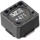
 | 7687709152 | SPEC | 10 files | Active i| Production is active. Expected lifetime: >10 years. | WE-PD HV SMT Power Inductor (High Voltage) | 1500 | 0.52 | – | 2.2 | 0.9 | – | 0.8 |
| Order Code | Datasheet | Simulation | |
|---|---|---|---|
 | 744732102 | SPEC | |
 | 7687709152 | SPEC |
| Samples |
|---|
| Order Code | Datasheet | Simulation | Downloads | Status | Product series | L (µH) | IR (A) | ISAT,10% (A) | RDC max. (Ω) | fres (MHz) | Version | ISAT (A) | Samples |
|---|


