Wolfspeed UCC2844D | Demoboard CRD-060DD17P-2
CRD-060DD17P-2: Auxiliary Power Supply evaluation board for C2M1000170J SiC MOSFET
Overview
| Topology | Flyback Converter |
| Input voltage | 300-1000 V |
| Output 1 | 12 V / 0.1 A |
| Output 2 | 12 V / 4 A |
Description
Three-phase applications, such as motor drive, UPS and PV inverter, have a front end AC/DC or DC/DC converter to boost the DC link voltage up to 600Vdc to 800Vdc. Factoring in a design margin, the maximum DC link voltage is up to 1000V. To support such systems in practice, an auxiliary power supply is used to generate power for cooling fans, displays, control logic and system protection functions with the DC link voltage as its input. For such low power applications, Flyback topology is the most common type in the industry; however, the conventional single end Flyback topology has difficulty in meeting high input voltage. The first difficulty is caused by the high input voltage (1000Vdc); the single-end Flyback topology would require high blocking voltage switching devices. Currently, the Silicon MOSFET only has 1500V blocking voltage, which has low voltage stress design margin and thus affects the reliability of the power supply. The second challenge is that most of the 1500V Si MOSFETs have very large on-state resistance, and this will lead to higher losses, higher thermal and lower efficiency, especially when the whole three-phase system is operating at light output load and auxiliary power losses occupy most of total system losses. Lastly, to support a wide input voltage range, a pure resistance start up circuit is normally used. However, the start-up resistance will lead to losses at high input voltage. Larger start-up resistance will have less losses but lead to long start-up time at low input voltage. In order to overcome these auxiliary power supply design challenges to supply high input voltage, two-switch Flyback converter was proposed to use high side and low side 800V Si MOSFETs as shown in Fig.1, but it has the additional isolation gate drive circuit which increases component counts and complicates the design. This application note proposes a single-end Flyback converter to replace complicated two-switch Flyback converter by using 1700V SiC MOSFET. An active start-up circuit is also introduced to achieve less start-up losses with faster start up time. The 60W experimental reference design demonstrates that the 1700V SiC MOSFET can reduce total cost and simplify the design of auxiliary power supply.
Features
A wide input, dual output, fly-back evaluation board designed to showcase the performance of a 1700V, 1 ohm SiC Wolfspeed MOSFET in a surface mount package (C2M1000170J).
More information
Products
| Order Code | Datasheet | Simulation | Downloads | Status | Product series | L (µH) | IRP,40K (A) | ISAT (A) | RDC max. (mΩ) | fres (MHz) | Size | Version | Samples | |
|---|---|---|---|---|---|---|---|---|---|---|---|---|---|---|
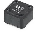
 | 744771003 | SPEC | 9 files | Active i| Production is active. Expected lifetime: >10 years. | WE-PD SMT Power Inductor | 3.5 | 14.5 | 9.5 | 8 | 40 | 1260 | Standard |
| Samples |
|---|
| Order Code | Datasheet | Simulation | Downloads | Status | Product series | L (µH) | IRP,40K (A) | ISAT (A) | RDC max. (mΩ) | fres (MHz) | Size | Version | Samples |
|---|


