IC manufacturers (103)
- All manufacturers
 Analog Devices
 Infineon Technologies
 Microchip
 Onsemi
 Renesas
 ROHM
ROHM STMicroelectronics
 Texas Instruments
- 3peak incorporated (28)
- Ablic (23)
- Acco Semiconductor (1)
- Advanced Power (4)
- Allegro Microsystems (100)
- Alpha & Omega Semiconductor (37)
- AnalogySemi (3)
- AnDAPT Inc (204)
- Anpec (13)
- AXElite (2)
- Backward (6)
- Bright Power Semiconductor (1)
- Broadcom (46)
- Cambridge GaN Devices (18)
- Chipanalog Micro (10)
- Cologne Chips (1)
- Convenient Power (1)
- Dialog Semiconductor (12)
- Diodes Incorporated (259)
- Divimath (8)
- Elmos AG (1)
- EPC (137)
- e-Peas Semiconductors (1)
- Eta Solutions Co. Ltd. (9)
- GaN Systems (8)
- GaNPower (3)
- Giantec (1)
- Gstek Wuxi (1)
- Helix Semiconductor (7)
- IKON (1)
- Indie Semiconductor (8)
- Innovision Semiconductor Inc (2)
- Intel (68)
- Inventchip Technology (3)
- ISSI (51)
- JoulWatt (20)
- KDPOF (3)
- Kinetic Technology (8)
- Lattice semiconductor Corporation (38)
- Littelfuse (1)
- Lumissil Microsystems (8)
- M3 Technology (M3Tek) (7)
- Macnica (22)
- Marvell Semiconductor (1)
- MaxLinear (181)
- Menlo Micro (1)
- MikroE (25)
- MindCet (2)
- Monolithic Power Systems (980)
- Navitas Semiconductor Inc (6)
- NewEdge Technologies, Inc. (1)
- Nexperia (267)
- Nisshinbo Micro Device Inc. (10)
- Novosense Micro (1)
- NXP (335)
- O2 Micro International Ltd (10)
- On Bright (7)
- Panasonic (2)
- PN Junction Semiconductor (2)
- Power Integrations (117)
- Powermat (1)
- Pulsiv (19)
- Qorvo (96)
- Realsil SuRealsil(tek) Microelectronics (1)
- Richtek (297)
- Sanken Electric Co., Ltd. (16)
- Sckipio (6)
- Semtech (86)
- SG-Micro (54)
- SiFive (2)
- Silanna Semiconductor (9)
- Silergy Corporation (33)
- Silicon Laboratory Inc. (108)
- Silicontent Technology (59)
- Silvertel (59)
- Skycore Semiconductors (1)
- Skyworks (33)
- Southchip (14)
- Summit Wireless (1)
- Tagore Tech (7)
- Taiwan Semiconductor (1)
- TDK Corporation (1)
- Tempo Semiconductor (1)
- Torex (37)
- Toshiba (25)
- Transphorm (21)
- TransSIP (2)
- Union (21)
- uPI Semiconductor (2)
- Valens Semiconductor (31)
- Wise Integration (3)
- Wolfspeed (23)
- Xilinx (22)
- XL Semiconductor (3)
- XYSemi (62)
Overview
| Topology | Buck Converter |
| Input voltage | 5.8-42 V |
| Switching frequency | 1850-2150 kHz |
| Output 1 | 5 V / 6 A |
| IC revision | 1 |
Description
Demonstration circuit 2658A is a 42V, 6A synchronousstep-down second generation SILENT SWITCHER withspread spectrum frequency modulation featuring theLT®8643S. The demo board is designed for 5V outputfrom a 5.8V to 42V input. The wide input range allows avariety of input sources, such as automotive batteries andindustrial supplies. The LT8643S is a compact, ultralowemission, high efficiency, and high speed synchronousmonolithic step-down switching regulator. The integratedbypass capacitors optimize all the fast current loops andmake it easier to minimize EMI/EMC emissions by reducinglayout sensitivity. Selectable spread spectrum mode canfurther improve EMI/EMC performance. Fast minimumon-time of 30ns enables high VIN to low VOUT conversionat high frequency.The LT8643S switching frequency can be programmedeither via oscillator resistor or external clock over a200kHz to 3MHz range. The default frequency of democircuit 2658A is 2MHz. The SYNC pin on the demo boardis grounded (JP1 at BURST position) by default for lowripple burst mode operation. To synchronize to an externalclock, move JP1 to SYNC and apply the external clock tothe SYNC terminal. Spread spectrum mode and forcedcontinuous mode can be selected respectively by movingJP1 shunt. Figure 1 shows the efficiency of the circuit at12V input and 24V input in Burst Mode Operation (inputfrom VIN terminal to bypass the EMI filter). Figure 2 shows the LT8643S temperature rising on DC2658A demo boardunder different load conditions. The rated maximum loadcurrent is 6A, while derating is necessary for certain inputvoltage and thermal conditions.The demo board has an EMI filter installed. The EMI performanceof the board (with EMI filter) is shown on Figure 3.The red line in Radiated EMI Performance is CISPR25 Class5 peak limit. The figure shows that the circuit passes thetest with a wide margin. To achieve EMI/EMC performanceas shown in Figure 3, the input EMI filter is required andthe input voltage should be applied at VIN_EMI terminal.An inductor can be added in the EMI filter to further reducethe conducted emission. The EMI filter can be bypassedby applying the input voltage at VIN terminal.The LT8643S data sheet gives a complete descriptionof the part, operation and application information. Thedata sheet must be read in conjunction with this demomanual for DC2658A. The LT8643S is assembled in a4mm × 4mm LQFN package with exposed pads for lowthermal resistance. The layout recommendations for lowEMI operation and maximum thermal performance areavailable in the data sheet section Low EMI PCB Layoutand Thermal Considerations and Peak Output Current.
More information
Products
Order Code | Datasheet | Simulation | Downloads | Status | Product series | f(mm) | Z @ 100 MHz(Ω) | Zmax(Ω) | Test Condition Zmax | IR(mA) | Z @ 1 GHz(Ω) | H(mm) | Type | Pins | Mount | L(mm) | Working Voltage(V (AC)) | Operating Temperature | Samples | |
|---|---|---|---|---|---|---|---|---|---|---|---|---|---|---|---|---|---|---|---|---|
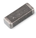 | WE-MPSB EMI Multilayer Power Suppression Bead, –, 100 Ω | Status Activei| Production is active. Expected lifetime: >10 years. | Product seriesWE-MPSB EMI Multilayer Power Suppression Bead | – | Impedance @ 100 MHz100 Ω | Maximum Impedance160 Ω | Maximum Impedance1100 MHz | Rated Current8000 mA | Impedance @ 1 GHz150 Ω | Height2.3 mm | TypeHigh Current | – | MountSMT | Length4.5 mm | – | Operating Temperature -55 °C up to +125 °C | ||||
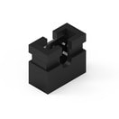
 | WA-SNSR Self-Retaining Spacer, 4.8 mm, – | Simulation– | Status Activei| Production is active. Expected lifetime: >10 years. | Product seriesWA-SNSR Self-Retaining Spacer | Drilling in Panel4.8 mm | – | – | – | – | – | – | – | – | – | Length12.7 mm | – | Operating Temperature -30 °C up to +85 °C | |||
 | WR-PHD Jumper, –, – | Simulation– | Status Activei| Production is active. Expected lifetime: >10 years. | Product seriesWR-PHD Jumper | – | – | – | – | Rated Current3000 mA | – | – | – | Pins2 | – | – | Working Voltage200 V (AC) | Operating Temperature -25 °C up to +105 °C | |||
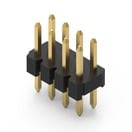 | WR-PHD Pin Header, –, – | Simulation– | Downloads7 files | Status Activei| Production is active. Expected lifetime: >10 years. | Product seriesWR-PHD Pin Header | – | – | – | – | Rated Current2000 mA | – | – | TypeStraight | Pins8 | MountTHT | Length8 mm | Working Voltage200 V (AC) | Operating Temperature -40 °C up to +105 °C |