IC manufacturers (104)
- All manufacturers
 Analog Devices
 Infineon Technologies
 Microchip
 Onsemi
 Renesas
 ROHM
ROHM STMicroelectronics
 Texas Instruments
- 3peak incorporated (28)
- Ablic (23)
- Acco Semiconductor (1)
- Advanced Power (4)
- Allegro Microsystems (97)
- Alpha & Omega Semiconductor (37)
- AnalogySemi (3)
- AnDAPT Inc (204)
- Anpec (13)
- AXElite (2)
- Backward (6)
- Bright Power Semiconductor (1)
- Broadcom (45)
- Cambridge GaN Devices (18)
- Chipanalog Micro (10)
- Cologne Chips (1)
- Convenient Power (1)
- Dialog Semiconductor (12)
- Diodes Incorporated (255)
- Divimath (8)
- Elmos AG (1)
- EPC (135)
- e-Peas Semiconductors (1)
- Eta Solutions Co. Ltd. (9)
- GaN Systems (8)
- GaNPower (3)
- Giantec (1)
- Gstek Wuxi (1)
- Helix Semiconductor (7)
- IKON (1)
- Indie Semiconductor (8)
- Innovision Semiconductor Inc (2)
- Intel (68)
- Inventchip Technology (3)
- ISSI (51)
- JoulWatt (20)
- KDPOF (3)
- Kinetic Technology (8)
- Lattice semiconductor Corporation (30)
- Littelfuse (1)
- Lumissil Microsystems (8)
- M3 Technology (M3Tek) (7)
- Macnica (22)
- Marvell Semiconductor (1)
- MaxLinear (181)
- Menlo Micro (1)
- MikroE (21)
- MindCet (2)
- Monolithic Power Systems (979)
- Navitas Semiconductor Inc (6)
- NewEdge Technologies, Inc. (1)
- Nexperia (263)
- Nisshinbo Micro Device Inc. (10)
- Nordic Semiconductor (1)
- Novosense Micro (1)
- NXP (327)
- O2 Micro International Ltd (10)
- On Bright (7)
- Panasonic (2)
- PN Junction Semiconductor (2)
- Power Integrations (120)
- Powermat (1)
- Pulsiv (19)
- Qorvo (95)
- Realsil SuRealsil(tek) Microelectronics (1)
- Richtek (297)
- Sanken Electric Co., Ltd. (16)
- Sckipio (6)
- Semtech (87)
- SG-Micro (49)
- SiFive (2)
- Silanna Semiconductor (9)
- Silergy Corporation (33)
- Silicon Laboratory Inc. (103)
- Silicontent Technology (59)
- Silvertel (61)
- Skycore Semiconductors (1)
- Skyworks (33)
- Southchip (8)
- Summit Wireless (1)
- Tagore Tech (7)
- Taiwan Semiconductor (1)
- TDK Corporation (1)
- Tempo Semiconductor (1)
- Torex (37)
- Toshiba (25)
- Transphorm (21)
- TransSIP (2)
- Union (21)
- uPI Semiconductor (2)
- Valens Semiconductor (30)
- Wise Integration (1)
- Wolfspeed (23)
- Xilinx (22)
- XL Semiconductor (3)
- XYSemi (62)
Overview
| Topology | Other Topology |
| Input voltage | 90-265 V |
| Output 1 | 12 V / 20 A |
Description
This evaluation board user’s manual provides basic information about a high efficiency, low no−load power consumption reference design that was tailored to power All−in−One PC or similar type of equipment that accepts 12 VDC on the input. The power supply implements PFC front stage to assure unity power factor and low THD, current mode LLC power stage to enhance transient response and secondary side synchronous rectification to maximize efficiency. This design note provides brief information about controllers’ implementation into design, their interconnections and cooperation. Please use links in literature section to get detail technical information about NCP1618, NCP13992, NCP4306 and NCP431. The NCP1618 is an innovative multimode power factor controller. The controller automatically change operation mode depending on conditions so that the efficiency is optimized over the line and load range. In very light−load conditions, the circuit enters a soft−skip cycle mode. NCP1618 enters Continuous Conduction Mode (CCM) under Heavy−Load Conditions, while Frequency−Clamped Critical Conduction Mode (FCCrM) is used for Medium− and Light−Load Conditions. PFC−OK Output serves as Brown−Out signal for LLC controller as well as communication interface which sends NCP1618 into stand−by mode (using Soft−skip cycles).
Features
- Wide Input Voltage Range
- PFC Controller with Multimode Operation
- High Efficiency/ Low No−load Power Consumption
- No Auxiliary SMPS, Fast Startup
- Near Unity Power Factor
- Low Mains & Overload Protection
- Thermal Protection
- Regulated Output Under any Conditions
- Excellent Load & Line Transient Response
- All Magnetics Available as Standard Parts
- Small Form Factor
- Extremely Low No−load Consumption
More information
Products
| Order Code | Datasheet | Simulation | Downloads | Status | Product series | Pins (pcs) | Application | PCB/Cable/Panel | Modularity | Type | Wire Section | C | VR (V (AC)) | Safety Class | dV/dt (V/µs) | DF @ 1 kHz (%) | RISO | Pitch (mm) | L (mm) | W (mm) | H (mm) | Packaging | Tol. C | Size | Qmin. | DF (%) | Ceramic Type | Fl (mm) | Operating Temperature | Q (%) | Endurance (h) | IRIPPLE (mA) | ILeak (µA) | Ø D (mm) | Ø Cable max. (mm) | Ø OD (mm) | Ø ID (mm) | Z @ 25 MHz 1 turn (Ω) | Z @ 100 MHz 1 turn (Ω) | Material | L (µH) | IR (A) | RDC max. (Ω) | Samples | |
|---|---|---|---|---|---|---|---|---|---|---|---|---|---|---|---|---|---|---|---|---|---|---|---|---|---|---|---|---|---|---|---|---|---|---|---|---|---|---|---|---|---|---|---|---|---|
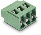 | 691236510002 | SPEC | – | 6 files | Active i| Production is active. Expected lifetime: >10 years. | WR-TBL Series 2365 - 5.08 mm Horiz. Entry w. Rising Cage Clamp | 2 | Rising Cage Clamp | PCB | Yes | Horizontal | 12 to 30 (AWG) 3.31 to 0.0509 (mm²) | – | – | – | – | – | – | 5.08 | 10.16 | – | – | Box | – | – | – | – | – | – | -30 °C up to +120 °C | – | – | – | – | – | – | – | – | – | – | – | – | 20 | – | |
 | 74270033 | SPEC | 2 files | Active i| Production is active. Expected lifetime: >10 years. | WE-AFB | – | – | – | – | – | – | – | – | – | – | – | – | – | 9.5 | – | – | – | – | – | – | – | – | – | -25 °C up to +125 °C | – | – | – | – | – | 4.4 | 9.5 | 4.75 | 47 | 68 | 3 W 800 | – | – | – | ||
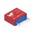 | 890324024002 | SPEC | 9 files | Active i| Production is active. Expected lifetime: >10 years. | WCAP-FTX2 Film Capacitors | – | Across the mains | – | – | – | – | 220 nF | 275 | X2 | 240 | 0.1 | 30 GΩ | 12.5 | 15 | 7 | 12.5 | Bulk | ±10% | Pitch 12.5 mm | – | – | – | – | -40 °C up to +105 °C | – | – | – | – | – | – | – | – | – | – | – | – | – | – | ||
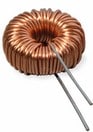 | 7447013 | SPEC | – | 8 files | Active i| Production is active. Expected lifetime: >10 years. | WE-FI Leaded Toroidal Line Choke | – | – | – | – | – | – | – | – | – | – | – | – | – | 18.5 | 10.5 | – | – | – | – | – | – | – | – | -40 °C up to +105 °C | – | – | – | – | – | – | – | – | – | – | – | 90 | 4.6 | 0.04 | |
 | 860010574011 | SPEC | 8 files | Active i| Production is active. Expected lifetime: >10 years. | WCAP-ATG8 Aluminum Electrolytic Capacitors | – | – | – | – | – | – | 220 µF | 35 | – | – | – | – | 3.5 | 11.5 | – | – | Ammopack | ±20% | – | – | 12 | – | – | – | – | 2000 | 385 | 77 | 8 | – | – | – | – | – | – | – | – | – | ||
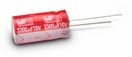 | 860040474004 | SPEC | 8 files | Active i| Production is active. Expected lifetime: >10 years. | WCAP-ATUL Aluminum Electrolytic Capacitors | – | – | – | – | – | – | 220 µF | 25 | – | – | – | – | 3.5 | 11.5 | – | – | Ammopack | ±20% | – | – | 14 | – | – | – | – | 7000 | 590 | 55 | 8 | – | – | – | – | – | – | – | – | – | ||
| 885012106018 | SPEC | 9 files | Active i| Production is active. Expected lifetime: >10 years. | WCAP-CSGP MLCCs 16 V(DC) | – | – | – | – | – | – | 2.2 µF | 16 | – | – | – | 0.05 GΩ | – | 1.6 | 0.8 | 0.8 | 7" Tape & Reel | ±20% | 0603 | 600 | 10 | X5R Class II | 0.4 | -55 °C up to +85 °C | – | – | – | – | – | – | – | – | – | – | – | – | – | – | |||
| 885012007052 | SPEC | 9 files | Active i| Production is active. Expected lifetime: >10 years. | WCAP-CSGP MLCCs 50 V(DC) | – | – | – | – | – | – | 15 pF | 50 | – | – | – | 10 GΩ | – | 2 | 1.25 | 0.6 | 7" Tape & Reel | ±5% | 0805 | – | – | NP0 Class I | 0.5 | -55 °C up to +125 °C | 700 | – | – | – | – | – | – | – | – | – | – | – | – | – | |||
| 885012007059 | SPEC | 9 files | Active i| Production is active. Expected lifetime: >10 years. | WCAP-CSGP MLCCs 50 V(DC) | – | – | – | – | – | – | 220 pF | 50 | – | – | – | 10 GΩ | – | 2 | 1.25 | 0.6 | 7" Tape & Reel | ±5% | 0805 | – | – | NP0 Class I | 0.5 | -55 °C up to +125 °C | 1000 | – | – | – | – | – | – | – | – | – | – | – | – | – | |||
| 885012007061 | SPEC | 9 files | Active i| Production is active. Expected lifetime: >10 years. | WCAP-CSGP MLCCs 50 V(DC) | – | – | – | – | – | – | 470 pF | 50 | – | – | – | 10 GΩ | – | 2 | 1.25 | 0.8 | 7" Tape & Reel | ±5% | 0805 | – | – | NP0 Class I | 0.5 | -55 °C up to +125 °C | 1000 | – | – | – | – | – | – | – | – | – | – | – | – | – | |||
| 885012007065 | SPEC | 9 files | Active i| Production is active. Expected lifetime: >10 years. | WCAP-CSGP MLCCs 50 V(DC) | – | – | – | – | – | – | 2.2 nF | 50 | – | – | – | 10 GΩ | – | 2 | 1.25 | 0.8 | 7" Tape & Reel | ±5% | 0805 | – | – | NP0 Class I | 0.5 | -55 °C up to +125 °C | 1000 | – | – | – | – | – | – | – | – | – | – | – | – | – | |||
| 885012007067 | SPEC | 9 files | Active i| Production is active. Expected lifetime: >10 years. | WCAP-CSGP MLCCs 50 V(DC) | – | – | – | – | – | – | 4.7 nF | 50 | – | – | – | 10 GΩ | – | 2 | 1.25 | 1.25 | 7" Tape & Reel | ±5% | 0805 | – | – | NP0 Class I | 0.5 | -55 °C up to +125 °C | 1000 | – | – | – | – | – | – | – | – | – | – | – | – | – | |||
| 885012207092 | SPEC | 9 files | Active i| Production is active. Expected lifetime: >10 years. | WCAP-CSGP MLCCs 50 V(DC) | – | – | – | – | – | – | 10 nF | 50 | – | – | – | 10 GΩ | – | 2 | 1.25 | 0.8 | 7" Tape & Reel | ±10% | 0805 | 600 | 2.5 | X7R Class II | 0.5 | -55 °C up to +125 °C | – | – | – | – | – | – | – | – | – | – | – | – | – | – | |||
| 885012207097 | SPEC | 9 files | Active i| Production is active. Expected lifetime: >10 years. | WCAP-CSGP MLCCs 50 V(DC) | – | – | – | – | – | – | 68 nF | 50 | – | – | – | 7.4 GΩ | – | 2 | 1.25 | 0.8 | 7" Tape & Reel | ±10% | 0805 | 600 | 2.5 | X7R Class II | 0.5 | -55 °C up to +125 °C | – | – | – | – | – | – | – | – | – | – | – | – | – | – | |||
| 885012207098 | SPEC | 9 files | Active i| Production is active. Expected lifetime: >10 years. | WCAP-CSGP MLCCs 50 V(DC) | – | – | – | – | – | – | 100 nF | 50 | – | – | – | 5 GΩ | – | 2 | 1.25 | 0.8 | 7" Tape & Reel | ±10% | 0805 | 600 | 2.5 | X7R Class II | 0.5 | -55 °C up to +125 °C | – | – | – | – | – | – | – | – | – | – | – | – | – | – | |||
| 885012207103 | SPEC | 9 files | Active i| Production is active. Expected lifetime: >10 years. | WCAP-CSGP MLCCs 50 V(DC) | – | – | – | – | – | – | 1 µF | 50 | – | – | – | 0.1 GΩ | – | 2 | 1.25 | 1.25 | 7" Tape & Reel | ±10% | 0805 | 600 | 10 | X7R Class II | 0.5 | -55 °C up to +125 °C | – | – | – | – | – | – | – | – | – | – | – | – | – | – | |||
| 885012208087 | SPEC | 9 files | Active i| Production is active. Expected lifetime: >10 years. | WCAP-CSGP MLCCs 50 V(DC) | – | – | – | – | – | – | 100 nF | 50 | – | – | – | 5 GΩ | – | 3.2 | 1.6 | 0.8 | 7" Tape & Reel | ±10% | 1206 | 600 | 2.5 | X7R Class II | 0.6 | -55 °C up to +125 °C | – | – | – | – | – | – | – | – | – | – | – | – | – | – | |||
| 750370249 | SPEC | – | – | Active i| Production is active. Expected lifetime: >10 years. | Power Inductor | – | – | – | – | – | – | – | – | – | – | – | – | – | – | – | – | – | – | – | – | – | – | – | – | – | – | – | – | – | – | – | – | – | – | – | – | – | – | ||
 | 885342007005 | SPEC | 8 files | Active i| Production is active. Expected lifetime: >10 years. | WCAP-CSMH Mid and High Voltage | – | – | – | – | – | – | 2.2 nF | 250 | – | – | – | 10 GΩ | – | 2 | 1.25 | 1.25 | 7" Tape & Reel | ±5% | 0805 | 1000 | – | NP0 Class I | 0.5 | -55 °C up to +125 °C | 1000 | – | – | – | – | – | – | – | – | – | – | – | – | – | ||
| 885342207006 | SPEC | 8 files | Active i| Production is active. Expected lifetime: >10 years. | WCAP-CSMH Mid and High Voltage | – | – | – | – | – | – | 22 nF | 200 | – | – | – | 4.545 GΩ | – | 2 | 1.25 | 1.25 | 7" Tape & Reel | ±10% | 0805 | – | 2.5 | X7R Class II | 0.5 | -55 °C up to +125 °C | 600 | – | – | – | – | – | – | – | – | – | – | – | – | – |
| Samples |
|---|
| Order Code | Datasheet | Simulation | Downloads | Status | Product series | Pins (pcs) | Application | PCB/Cable/Panel | Modularity | Type | Wire Section | C | VR (V (AC)) | Safety Class | dV/dt (V/µs) | DF @ 1 kHz (%) | RISO | Pitch (mm) | L (mm) | W (mm) | H (mm) | Packaging | Tol. C | Size | Qmin. | DF (%) | Ceramic Type | Fl (mm) | Operating Temperature | Q (%) | Endurance (h) | IRIPPLE (mA) | ILeak (µA) | Ø D (mm) | Ø Cable max. (mm) | Ø OD (mm) | Ø ID (mm) | Z @ 25 MHz 1 turn (Ω) | Z @ 100 MHz 1 turn (Ω) | Material | L (µH) | IR (A) | RDC max. (Ω) | Samples |
|---|
